 DC Motor B2B
What Is a Geared Servo Motor and How Does It Work?
A Geared Servo Motor combines a servo motor’s precise control with a gearbox’s mechanical advantage. This arrangement helps machines produce higher torque at lower output speeds. It is widely used in robotics, packaging equipment, CNC machinery, conveyors, and automated production lines. The motor receives control signals from a drive or controller. Its encoder reports shaft position and speed in real time. The controller then corrects movement when the actual position differs from the target.
The gearbox changes the motor’s speed and torque characteristics. For example, a reduction gear may turn several rapid motor rotations into one slower output rotation. This creates stronger movement, but it can also introduce backlash, friction, heat, and efficiency losses. These details matter during equipment selection. A system that looks powerful on paper may perform poorly if its gears are overloaded or poorly lubricated. In practical installations, engineers check torque demand, acceleration, duty cycle, positioning accuracy, and operating temperature. They also consider cable routing, encoder feedback, and maintenance access.
Small errors matter.
A reliable Geared Servo Motor is not chosen by torque alone. Manufacturers’ specifications, load calculations, application testing, and qualified technical guidance should support the decision. Gear ratio, motor size, and control tuning must work together. Sometimes, designers underestimate reflected inertia or assume perfect gearbox efficiency. That assumption deserves review. Understanding how each component interacts allows engineers to build quieter, safer, and more responsive motion systems.
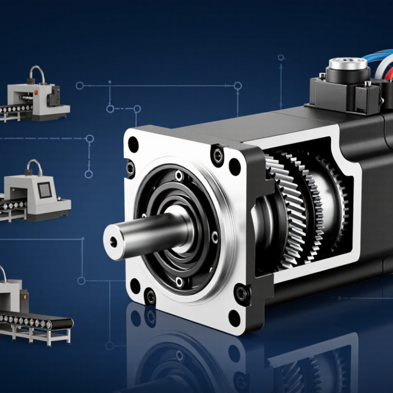
Definition and Core Components of a Geared Servo Motor
A geared servo motor is a servo motor combined with a gearbox. It delivers controlled motion with higher torque and lower output speed. This arrangement suits robotic joints, conveyor mechanisms, and precision positioning equipment. The motor creates rotational force, while the gearbox changes that force into usable output motion. In practical systems, the gearbox is not an optional detail. It strongly affects speed, torque, accuracy, noise, and service life.
The core components include the electric motor, gear train, encoder, servo drive, bearings, and protective housing. The motor supplies rotation, usually at high speed. The gear train reduces speed and increases output torque. Planetary, spur, and harmonic gear arrangements behave differently under load. An encoder measures shaft position or speed. The servo drive compares this feedback with the target command. It then adjusts current to correct the error. The housing protects internal parts from dust and accidental contact. Bearings support the rotating shafts and limit unwanted movement.
The process is continuous. A controller requests a position. The motor turns. The encoder reports movement. The drive checks the difference and responds within milliseconds. Small details matter here. Gear backlash can create a slight positioning delay, especially when direction changes. Lubrication, mounting stiffness, and operating temperature also influence performance. I have found that specifications alone can mislead engineers. A motor may show impressive torque, yet lose accuracy under repeated shock loads. Careful testing under the real load remains essential.
| Dimension | Definition or Component | How It Works | Practical Function and Considerations |
|---|---|---|---|
| Basic Definition | A geared servo motor is a closed-loop motion-control actuator that combines an electric motor, a gear train, a feedback device, and a control circuit. | The motor produces rotational motion, while the controller compares the commanded position with the measured position and corrects any error. | It is designed for controlled position, speed, or torque rather than simple continuous rotation alone. |
| Electric Motor | The motor is the prime mover, commonly using a permanent-magnet brushed DC, brushless DC, or synchronous design. | Electrical energy creates electromagnetic torque that turns the motor shaft. | Motor selection affects speed range, efficiency, thermal performance, noise, maintenance, and achievable torque. |
| Gearbox | The gearbox is a mechanical transmission positioned between the motor and the output shaft. | Gears reduce motor speed and multiply output torque according to the reduction ratio, while transmitting motion to the load. | Common gear arrangements include spur, planetary, worm, and harmonic or strain-wave mechanisms. Each design involves trade-offs in efficiency, backlash, size, and load capacity. |
| Gear Reduction Ratio | The reduction ratio describes the relationship between motor speed and output speed, such as 10:1. | With a 10:1 reduction, the output typically turns at about one-tenth of the motor speed, while ideal output torque is approximately ten times the motor torque before losses. | Actual torque is lower than the ideal value because of gear-mesh friction, bearing losses, seal drag, and other mechanical inefficiencies. |
| Feedback Device | An encoder, potentiometer, resolver, or similar sensor measures shaft position, speed, or direction. | The feedback signal is sent to the controller, which uses it to determine the difference between the target value and the actual motion. | Encoders generally provide digital position information, while potentiometers provide an analog position signal. Feedback accuracy influences positioning performance. |
| Servo Controller | The controller is the electronic unit that processes the command signal and feedback signal. | It adjusts motor voltage, current, or switching signals to reduce position, speed, or torque error. | Control methods may include proportional, integral, and derivative functions, commonly known as PID control, along with current and speed control loops. |
| Output Shaft | The output shaft is the mechanical interface that transfers the geared motor’s motion to the driven load. | It rotates at the reduced speed and increased torque produced by the gearbox. | The shaft must be sized for radial loads, axial loads, torsional loads, and the required duty cycle. Coupling alignment is important for reducing vibration and wear. |
| Position Control | Position control commands the output shaft to move to and hold a defined angular or linear position. | The controller continuously compares the target position with feedback from the sensor and applies corrective motion. | Gear reduction can improve resolution at the output, but backlash and compliance may limit absolute positioning accuracy. |
| Speed Control | Speed control regulates how fast the output shaft rotates. | The controller compares the requested speed with the measured speed and adjusts motor power to compensate for load changes. | Stable speed control is useful in conveyors, rotary tables, feeders, and other applications requiring consistent motion. |
| Torque Capability | Torque capability is the rotational force available at the gearbox output. | Gear reduction increases available output torque while reducing output speed; the usable value is limited by motor torque, gear strength, thermal conditions, and efficiency. | Designers should distinguish between continuous torque, intermittent torque, peak torque, and stall torque when sizing a geared servo motor. |
| Backlash | Backlash is the small amount of lost motion caused by clearance between mating gear teeth and mechanical parts. | When the direction of rotation changes, the motor may move slightly before the output shaft responds. | Low-backlash gearboxes are preferred for precision positioning, robotics, indexing, and applications with frequent direction reversals. |
| Efficiency | Efficiency is the ratio of mechanical power delivered at the output to electrical and mechanical power supplied to the system. | Energy is lost through electrical resistance, switching, bearing friction, gear-mesh friction, and lubricant drag. | Higher reduction ratios and certain gear types can increase losses. Efficiency affects heat generation, power consumption, and continuous operating capacity. |
| Closed-Loop Operation | Closed-loop operation means that the system uses real-time feedback instead of relying only on a preset motor command. | The controller repeatedly measures the output condition, calculates error, and updates the drive signal. | This allows the system to compensate for moderate changes in load, friction, and operating conditions, provided the actuator remains within its rated limits. |
| Electrical Supply | The power supply provides the voltage and current required by the motor and control electronics. | The driver converts the supplied electrical power into controlled motor current or switching signals. | Voltage, peak current, continuous current, connector design, and protection against overcurrent or overheating must match the motor and controller requirements. |
| Thermal Management | Thermal management controls heat generated by the motor, gearbox, electronics, and bearings. | Heat is transferred through the housing, mounting structure, airflow, or dedicated cooling equipment. | Excessive temperature can reduce insulation life, degrade lubricant, lower available torque, and shorten component service life. |
| Typical Applications | Geared servo motors are used where controlled motion and increased output torque are required in a compact package. | The actuator follows programmed position, speed, or torque commands while feedback helps maintain the desired operating state. | Typical uses include robotic joints, automated machinery, packaging equipment, machine tools, pick-and-place systems, camera positioning, and precision rotary mechanisms. |
| Key Selection Criteria | Selection requires matching the actuator to the load, motion profile, environment, and control system. | Engineers evaluate speed, continuous and peak torque, inertia, acceleration, backlash, duty cycle, accuracy, mounting dimensions, and feedback compatibility. | Correct sizing prevents overheating, excessive vibration, missed positions, premature gear wear, and insufficient dynamic performance. |
FAQS
It combines an electric servo motor with a mechanical gearbox. The motor rotates quickly, while the gearbox produces slower, stronger output motion. This design suits robotic joints, conveyors, and positioning equipment.
A 10:1 reduction makes the output turn about one-tenth as fast. Output torque may approach ten times motor torque, minus mechanical losses. The trade-off is slower movement.
Key parts include the motor, gear train, encoder, servo drive, bearings, and protective housing. The encoder measures position or speed. The drive compares feedback with the requested movement and adjusts current.
Feedback helps the system correct position errors within milliseconds. It can detect small differences between commanded and actual movement. Without suitable feedback, accuracy may suffer under changing loads.
Backlash is a small movement gap between gear teeth. It can cause delayed motion when direction changes. A worn gear train may feel soft before the load starts moving.
No. A higher ratio can increase holding force and output torque. It can also reduce speed and extend settling time. The best ratio depends on load, motion, and duty cycle.
Mounting stiffness, cable drag, lubrication, temperature, and reflected inertia all matter. Shock loads can reduce accuracy despite impressive specifications. Catalog calculations are useful, but they are not reality.
Test it with the actual load, operating cycle, and mounting arrangement. Watch temperature, noise, settling time, and repeated positioning. Small details matter. Results may still vary, so further measurement is wise.
Conclusion
A Geared Servo Motor combines a servo motor, gear train, feedback device, and control electronics to deliver precise, stable motion. The gear system adjusts the motor’s speed and torque, typically reducing output speed while increasing usable torque and improving control at the load. During operation, the controller compares the commanded position, speed, or torque with feedback from the sensor, then continuously corrects the motor’s movement to reduce error and maintain accurate performance.
Important specifications include rated torque, peak torque, speed range, gear ratio, positioning accuracy, backlash, response time, duty cycle, and efficiency. Control methods may include position, velocity, or torque control, depending on the application. Geared Servo Motor systems are commonly used in robotic mechanisms, automation equipment, conveyor systems, medical devices, and precision machinery. Selecting the right unit requires evaluating load inertia, required motion profile, operating environment, mounting space, noise, maintenance needs, and compatibility with the control system.
