DC Motor B2B
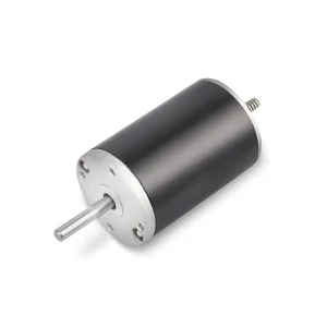
Featured High-Performance Brushless Motors
Engineered for high speed, absolute thermal stability, and maximum torque density in space-constrained micro designs.
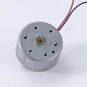
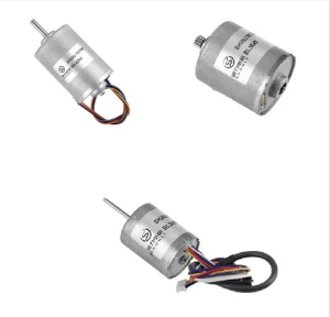
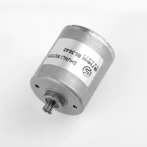
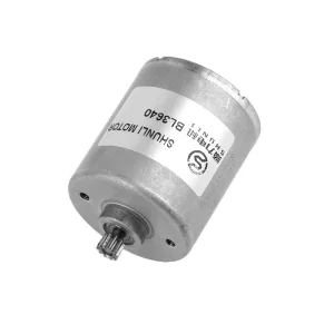
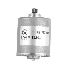
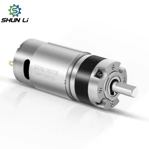
ABOUT: Packing Massive Torque Into Miniature Spaces
Inside a premium robotic joint, an automated medical pump, or a high-end smart lock, space is the ultimate luxury. At DQC, we measure our success in micrometers and decibels. Our mission is to take advanced, heavy-duty rotational power and compress it into the most compact, energy-efficient footprints imaginable.
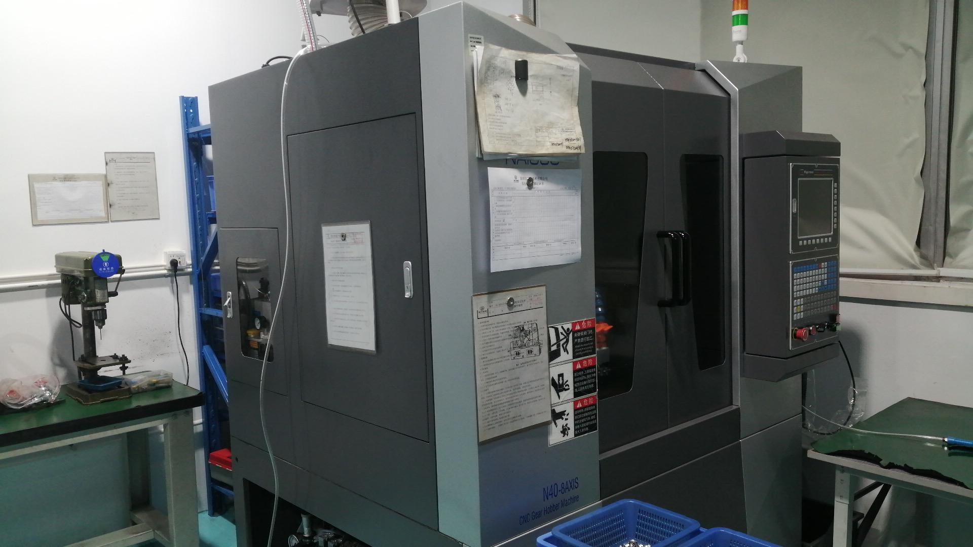
Our expertise lies in the micro-details of motion. From precision-wound copper rotors and high-purity commutators to zero-backlash planetary gear trains, every single internal component of a DQC motor is optimized to eliminate friction and maximize heat dissipation. By combining advanced automated Swiss-style hobbing with Japanese dynamic balancing, we ensure our micro drives deliver the fluid, whispering-quiet power your brand promises. When your next high-tech innovation relies on repeated mechanical perfection, let DQC be the core that spins it forward.
Technical Roadmap: The Evolution of Micro Brushless DC Motors
In modern industrial design, the transition from brushed direct current (DC) motors to Brushless DC (BLDC) motors represents a fundamental shift in efficiency and longevity. Traditional brushed motors rely on physical carbon brushes that wear down over time, causing electrical noise, friction, and thermal accumulation. A brushless motor solves this limitation by electronically commutating the phases. Using Hall-effect sensors or back-electromotive force (Back-EMF) sensing, the controller regulates power input directly to the stator windings, allowing the permanent magnet rotor to spin with minimal mechanical resistance.
Modern Micro BLDC Topology: Inner Rotor vs. Outer Rotor
Selecting the correct motor topology depends heavily on the torque profile and speed requirements of your application:
- Inner Rotor BLDC: Features the permanent magnets mounted on the central shaft, surrounded by stator windings. This design yields low rotor inertia, enabling ultra-fast acceleration, high rotational speeds (often exceeding 20,000 RPM), and rapid dynamic response. Typical applications include micro medical fans, high-velocity hair dryers, and remote control (RC) aviation systems.
- Outer Rotor BLDC (Outrunner): The stator windings reside in the center, while the outer bell contains the permanent magnets. This design generates a larger air-gap radius, resulting in substantially higher torque constants (Kt) at lower speeds. This makes outer rotor models ideal for direct-drive applications like high-end blender drives, robotic joints, and active gimbal stabilizers.
| Parameters & Metrics | Brushed DC Motor (BDC) | Standard Inner Rotor BLDC | Custom Outer Rotor BLDC |
|---|---|---|---|
| Operational Lifespan (hours) | 1,000 – 3,000 (limited by brushes) | 15,000 – 30,000+ (bearing limited) | 20,000 – 40,000+ |
| Electromagnetic Interference (EMI) | High (brush sparking) | Negligible | Negligible |
| Maintenance Complexity | High periodic replacement | Zero maintenance required | Zero maintenance required |
| Heat Dissipation Location | Rotor (hard to dissipate) | Stator (exterior frame, highly efficient) | Stator core (stable thermal envelope) |
| Optimal Applications | Low-cost toys, basic locks | High-speed hair dryers, medical pumps | Robotic joints, industrial blenders |
Magnetic Steel Engineering: Choosing NdFeB vs. SmCo
The performance of a high-torque brushless DC motor is fundamentally constrained by its permanent magnets. At our factory, we primarily utilize Neodymium-Iron-Boron (NdFeB) magnets, which provide the highest magnetic energy product (BHmax) currently available. However, for specialized industrial applications that experience operating temperatures above 150°C, we design custom rotors utilizing Samarium-Cobalt (SmCo) magnets. While SmCo possesses a slightly lower energy density, it exhibits exceptional thermal stability and resistance to demagnetization under harsh electrical loads.
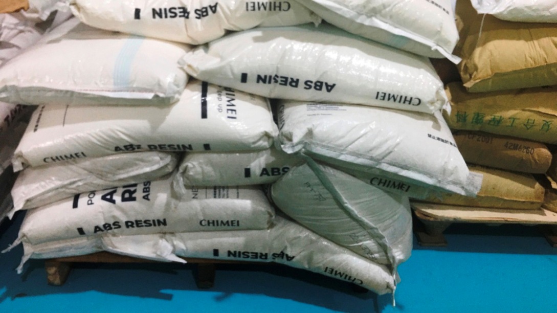
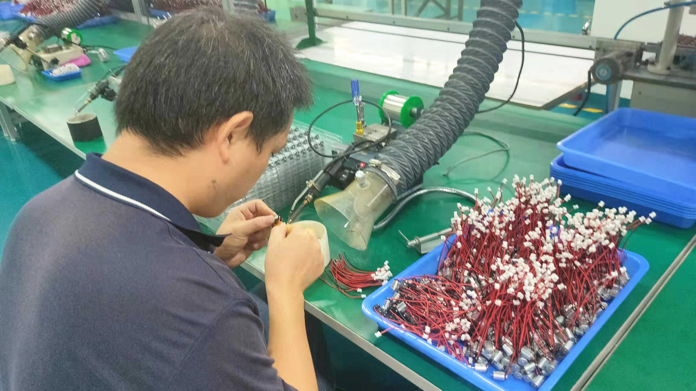
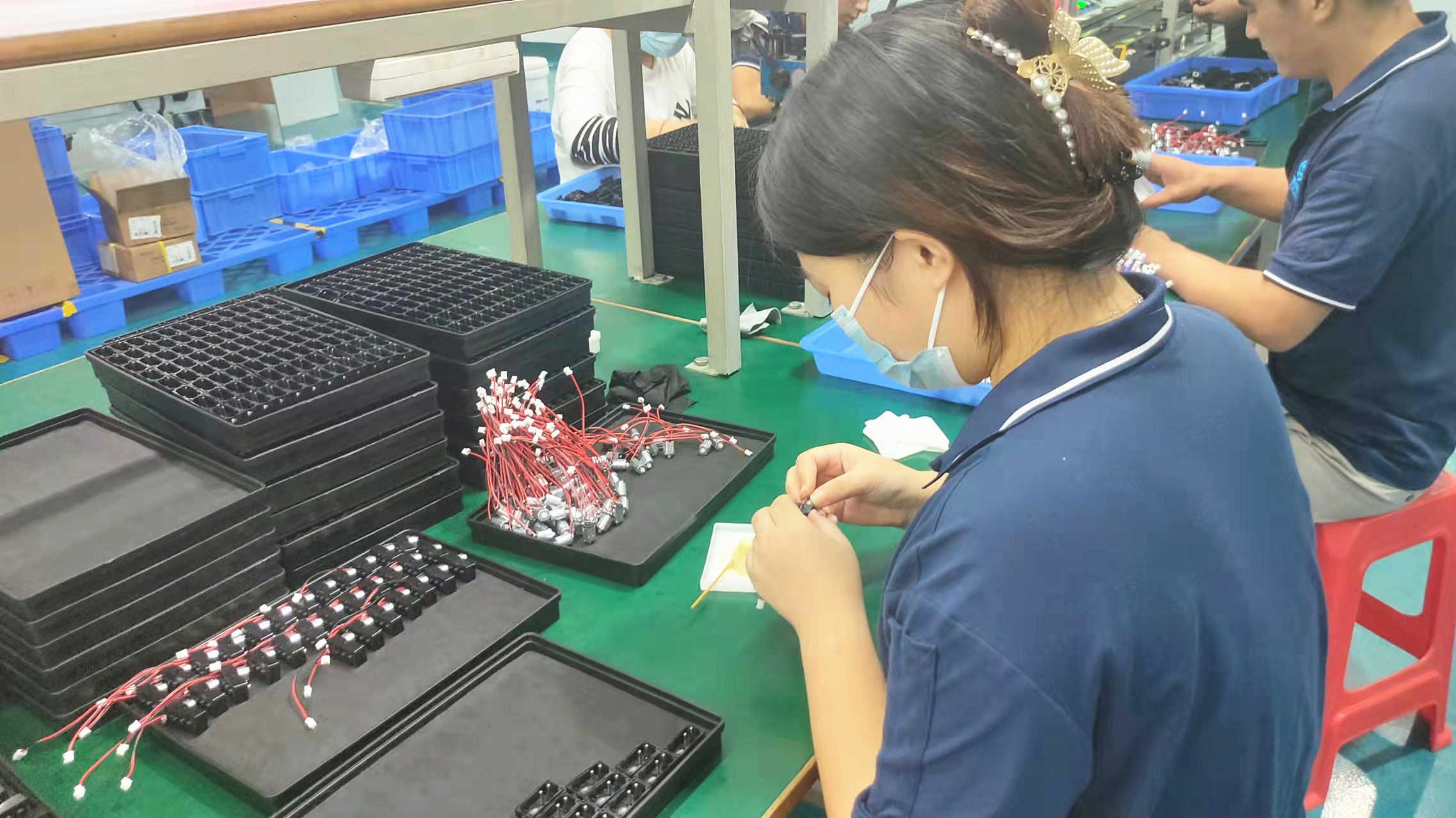
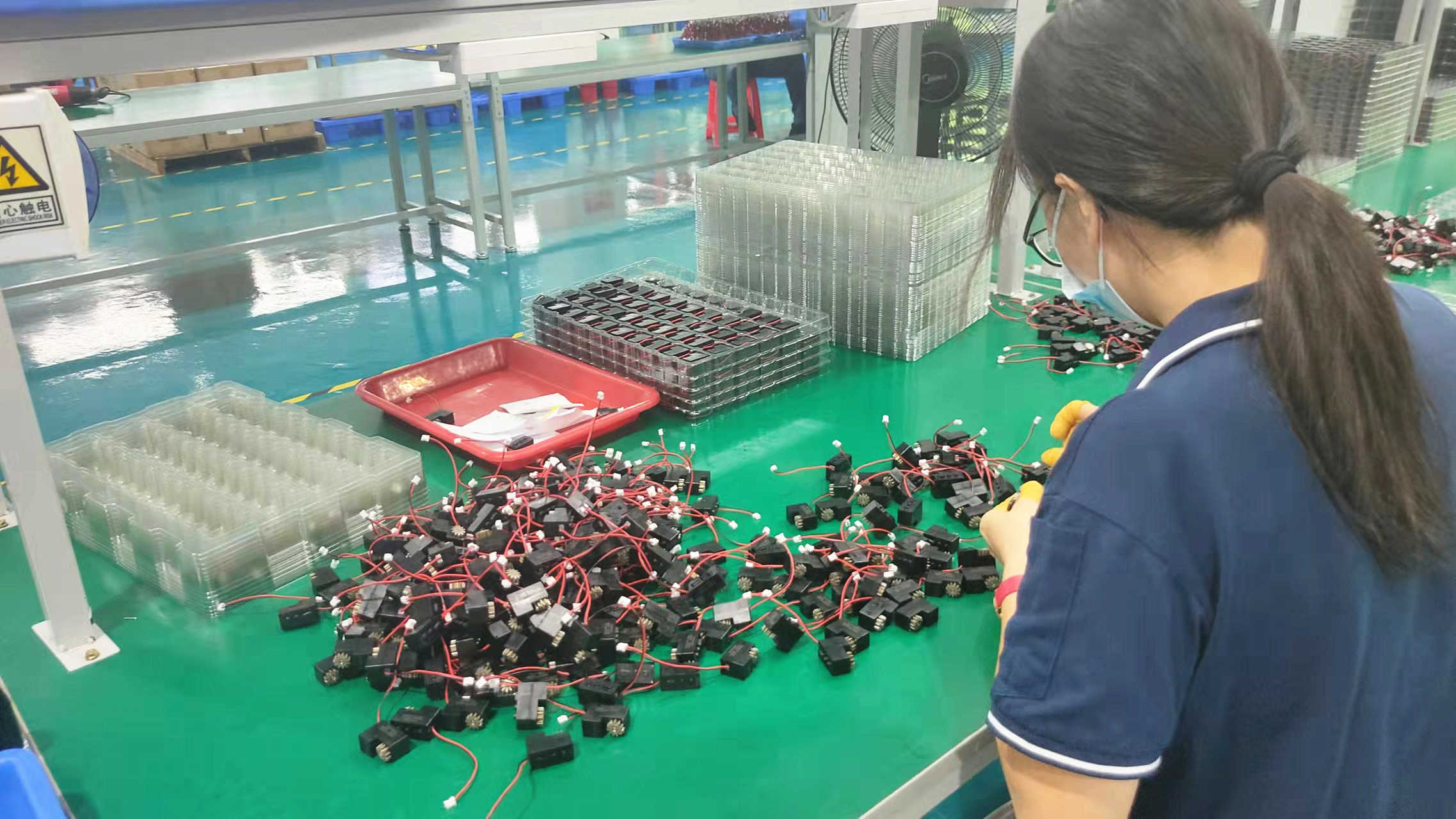
Six-Stage Factory Manufacturing Blueprint
Every motor produced under the DQC standard undergoes a highly regulated sequence of fabrication, ensuring mechanical consistency across large-scale production runs.
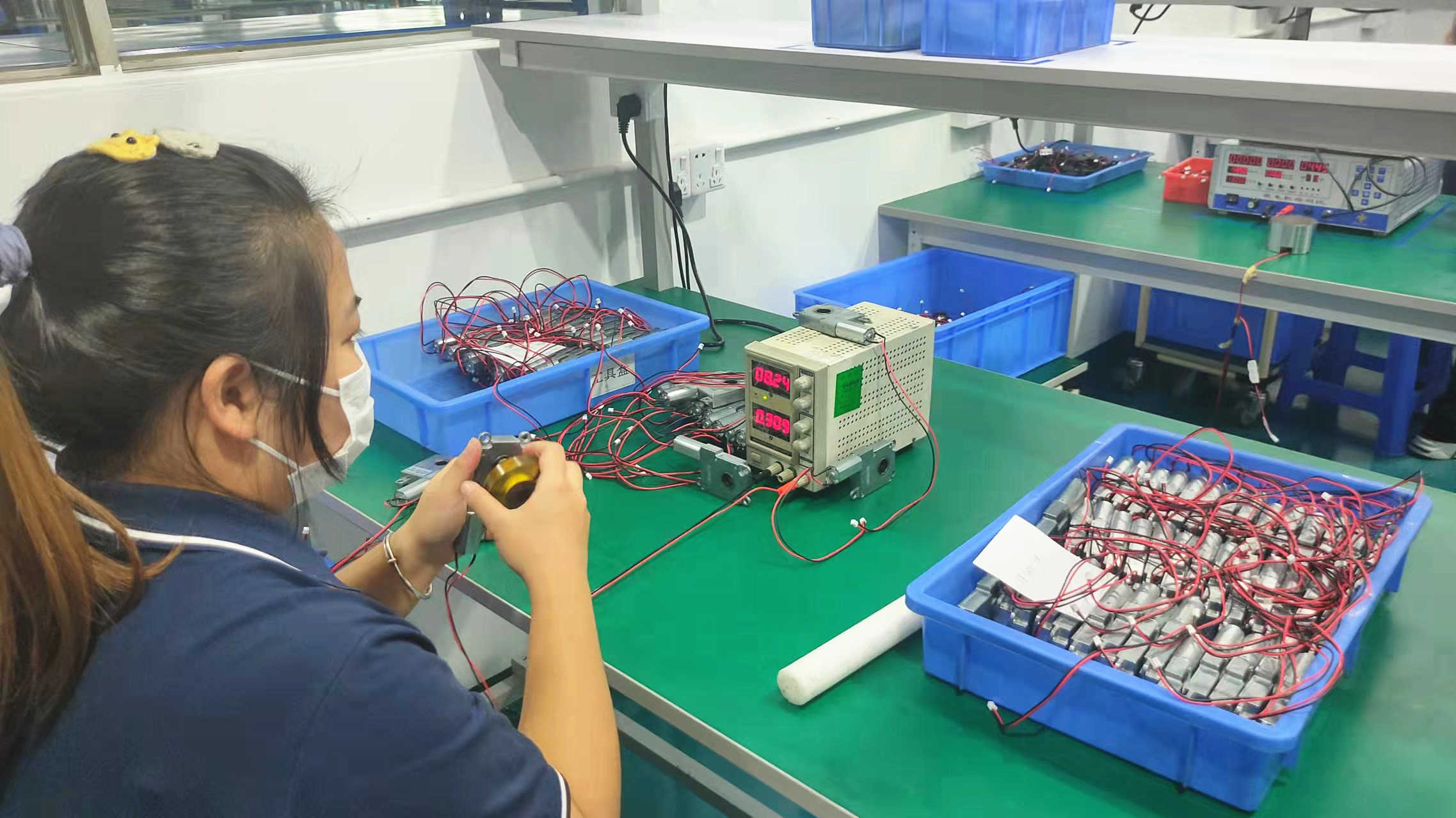
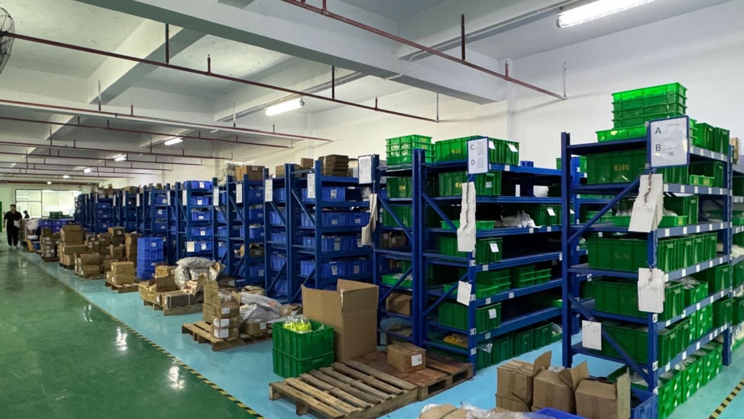
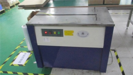
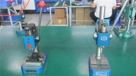
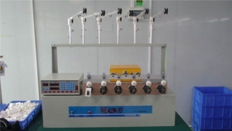
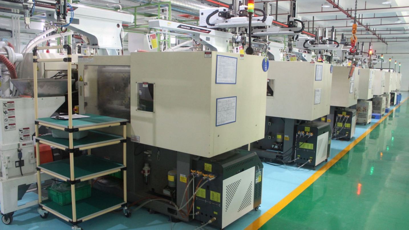
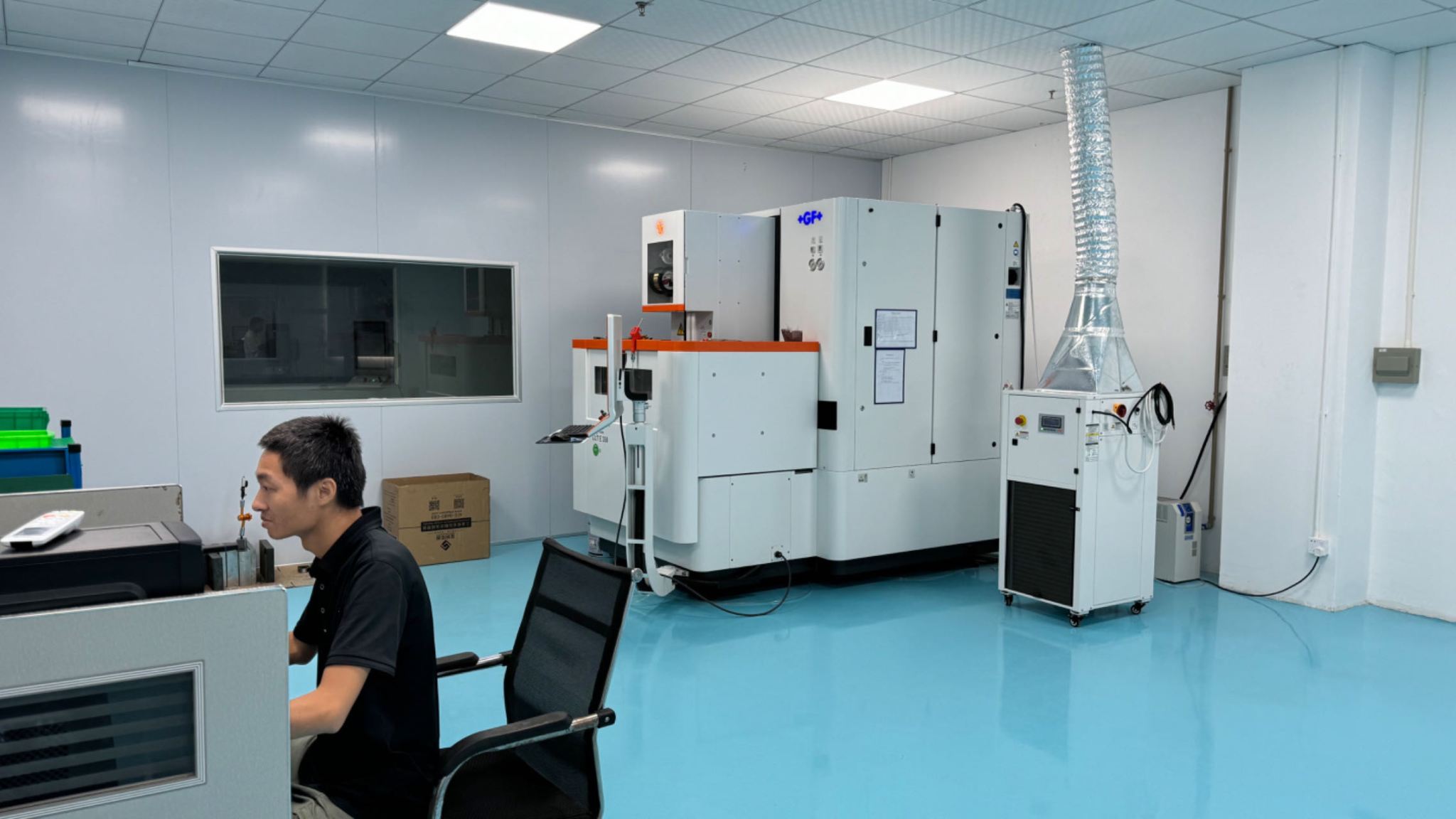
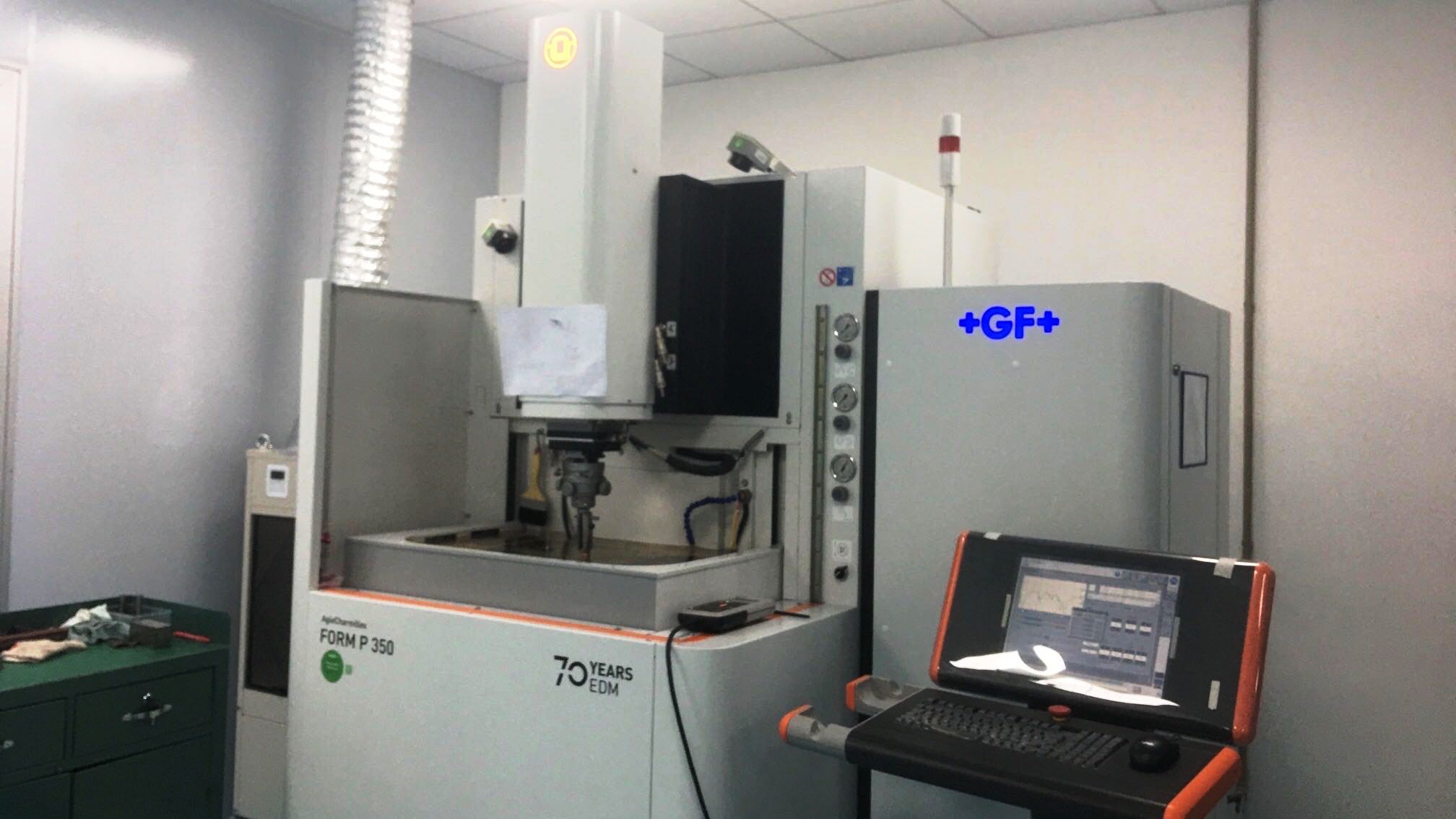
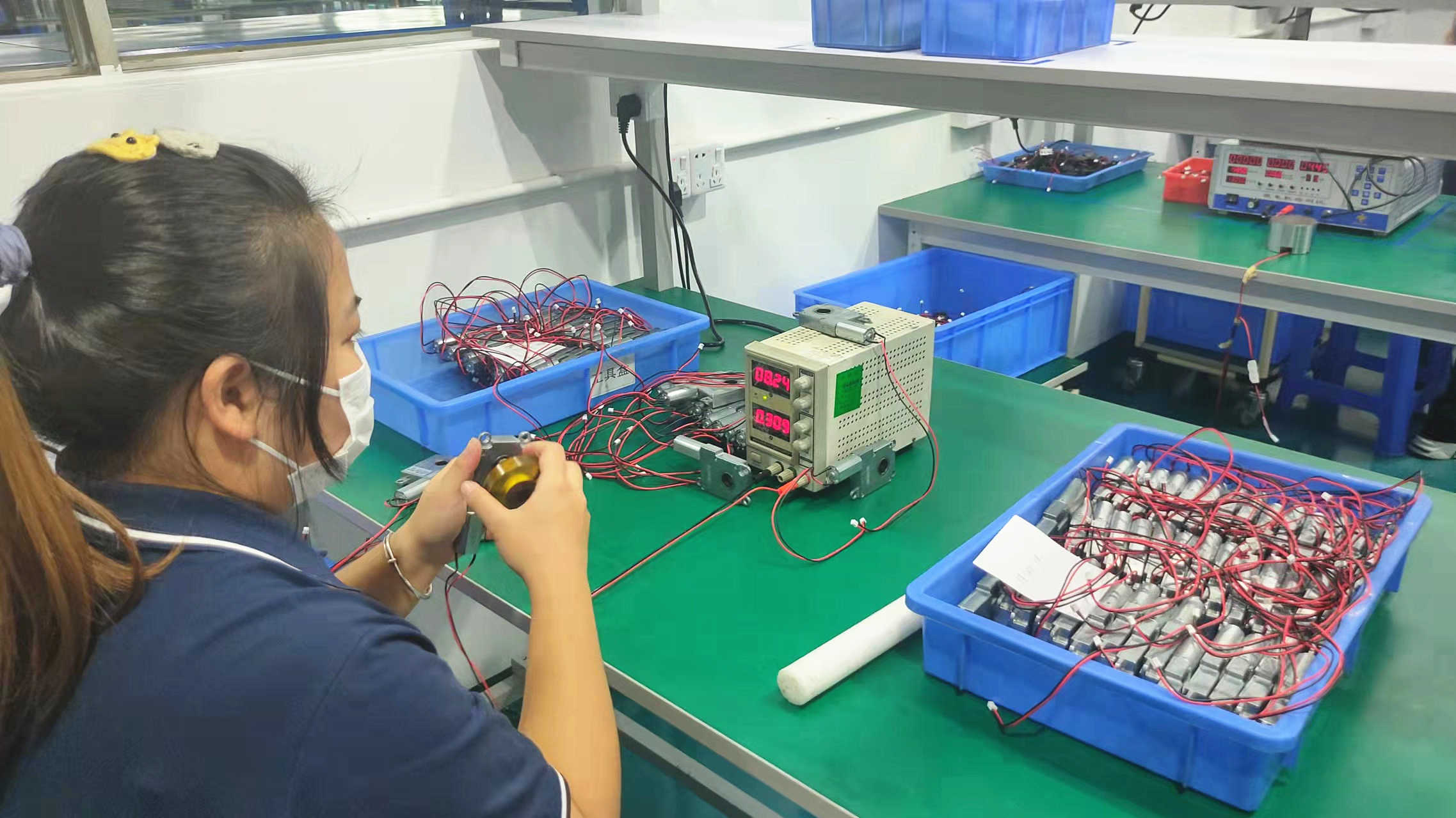
Advanced Manufacturing Infrastructure
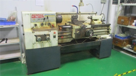
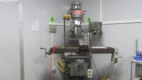
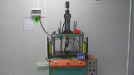
Our facility houses high-precision CNC machinery and automated winding systems to keep manufacturing tolerances within single-digit microns.
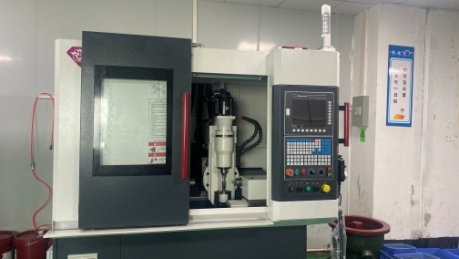
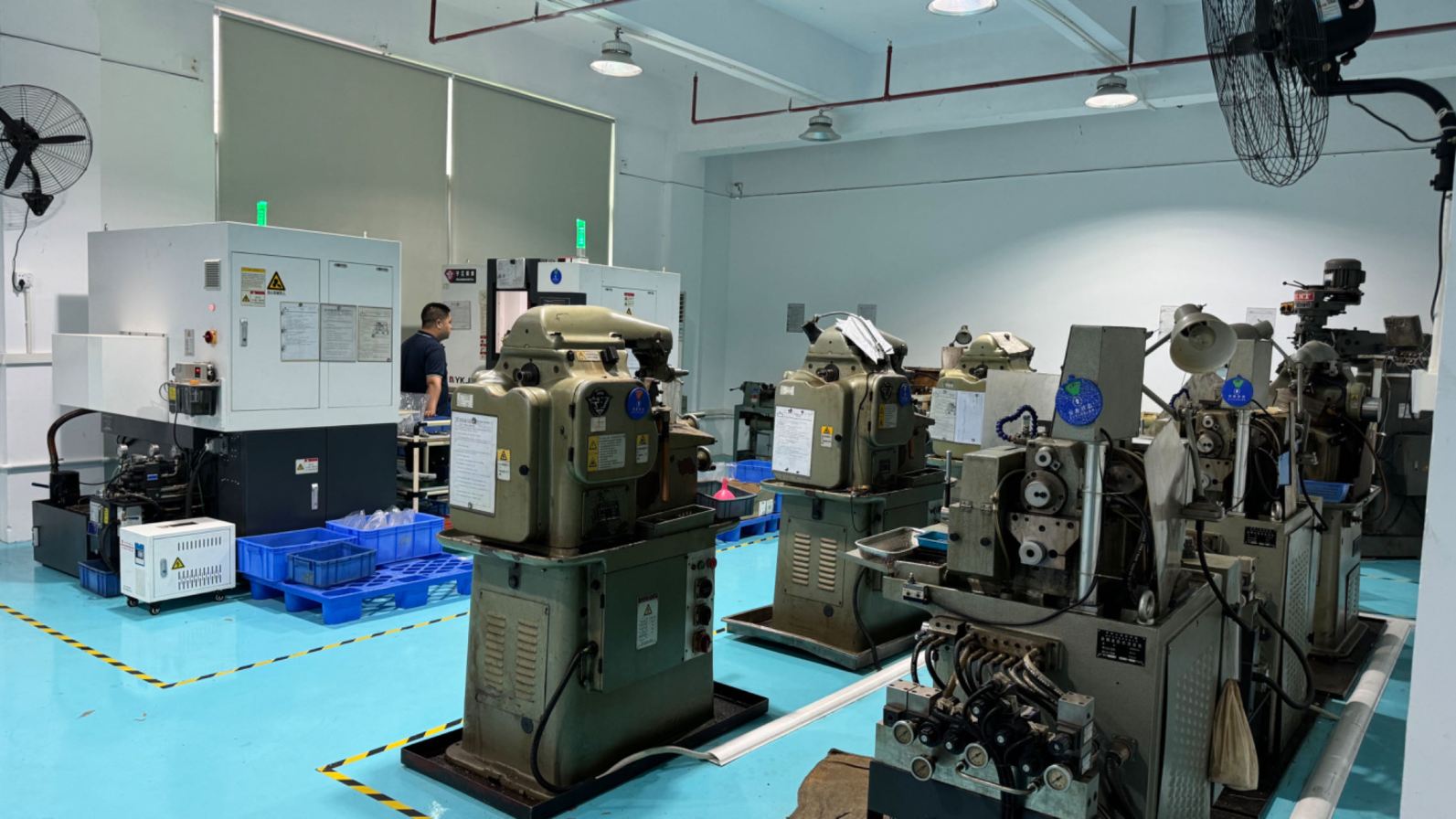
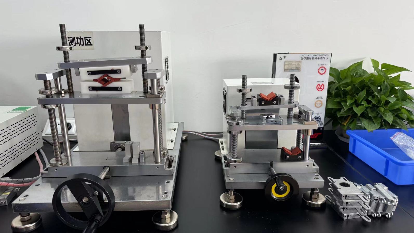
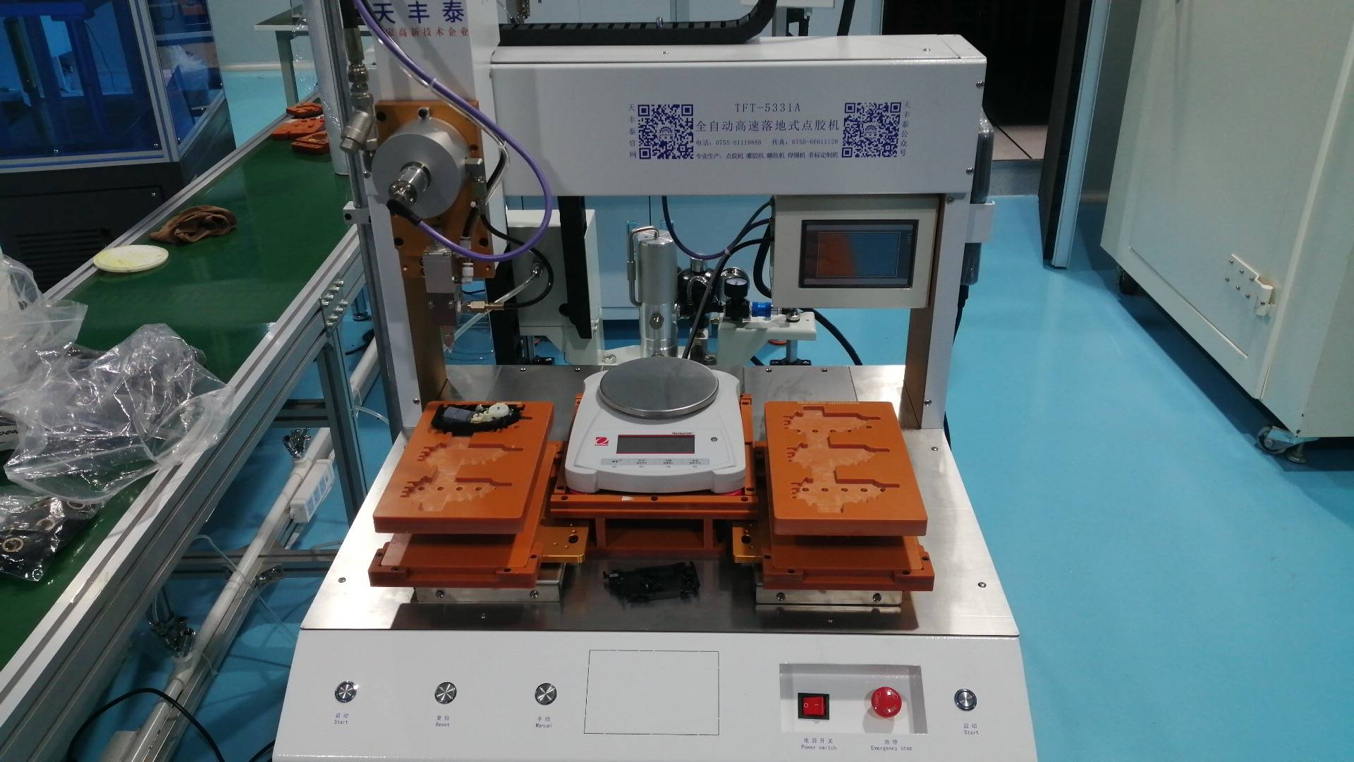
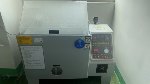
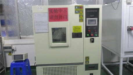
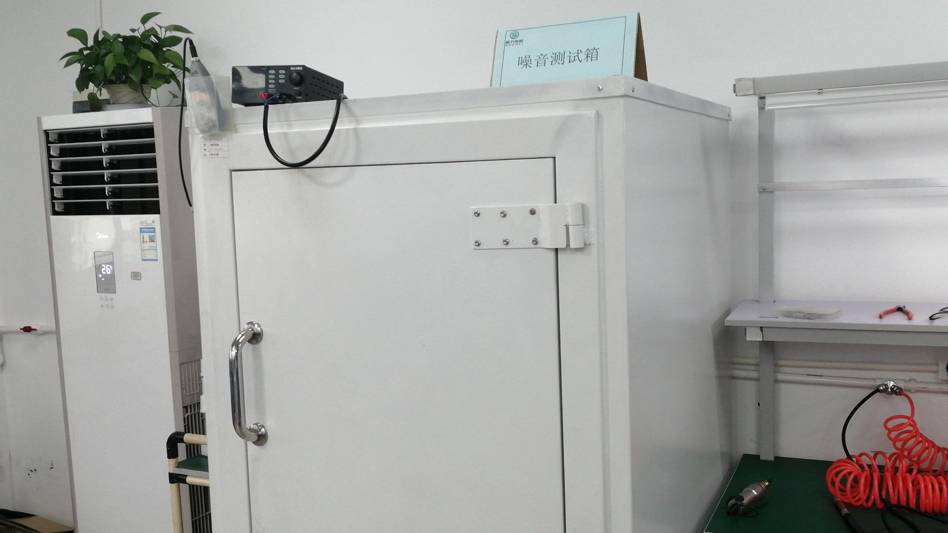
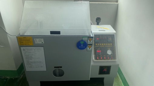
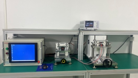
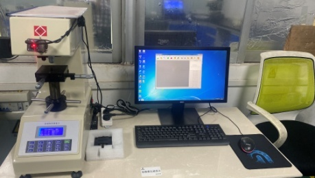
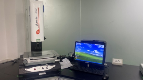
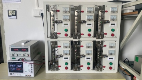
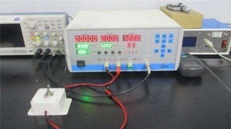
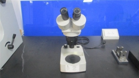
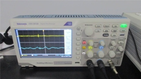
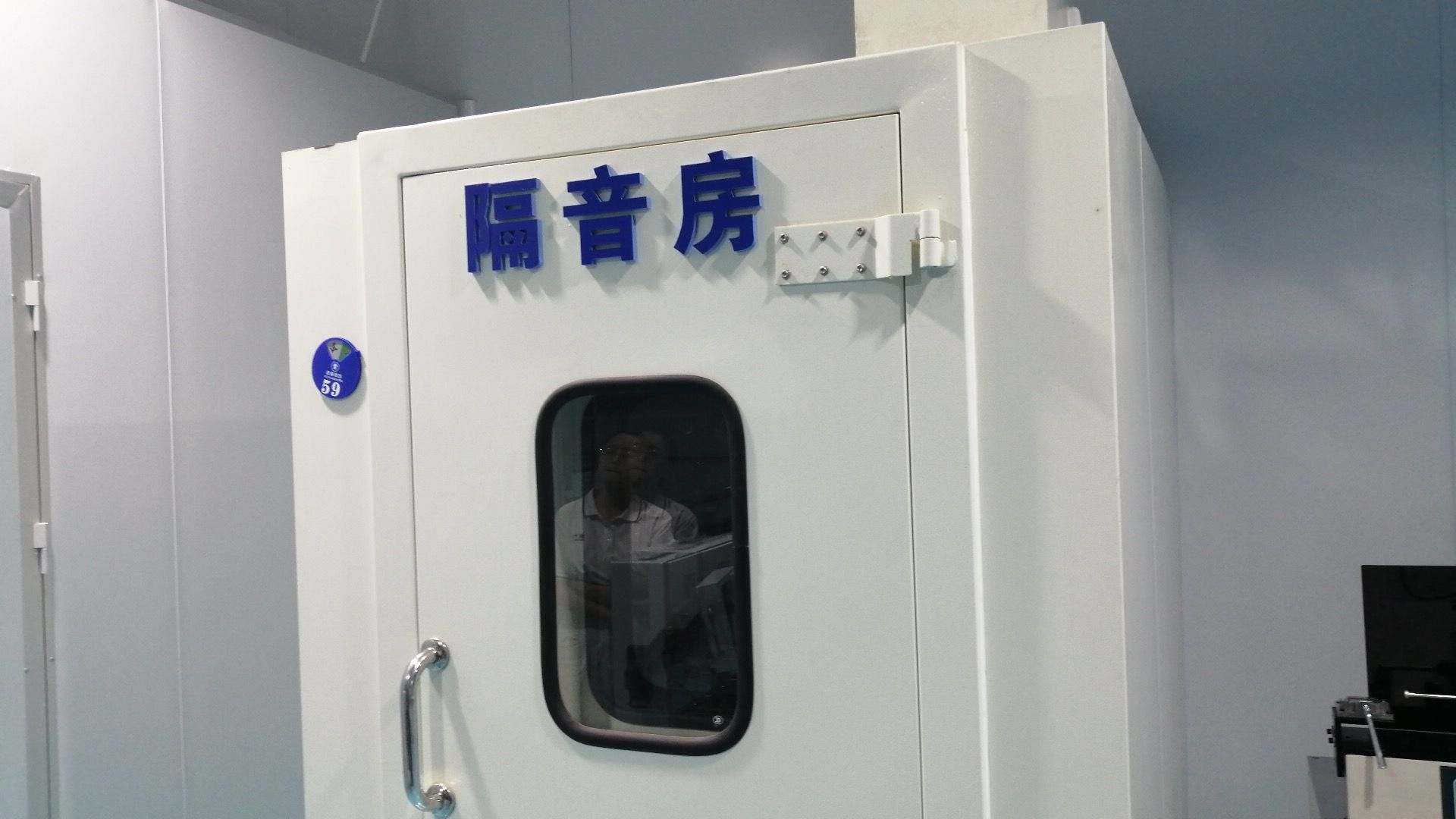
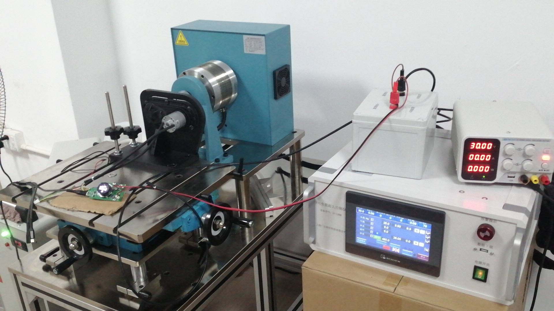
Metrology Laboratory & Advanced Quality Assurance
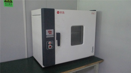
From simulated environmental weathering to dynamometer performance mapping, our quality control ensures reliability under heavy industrial operation.
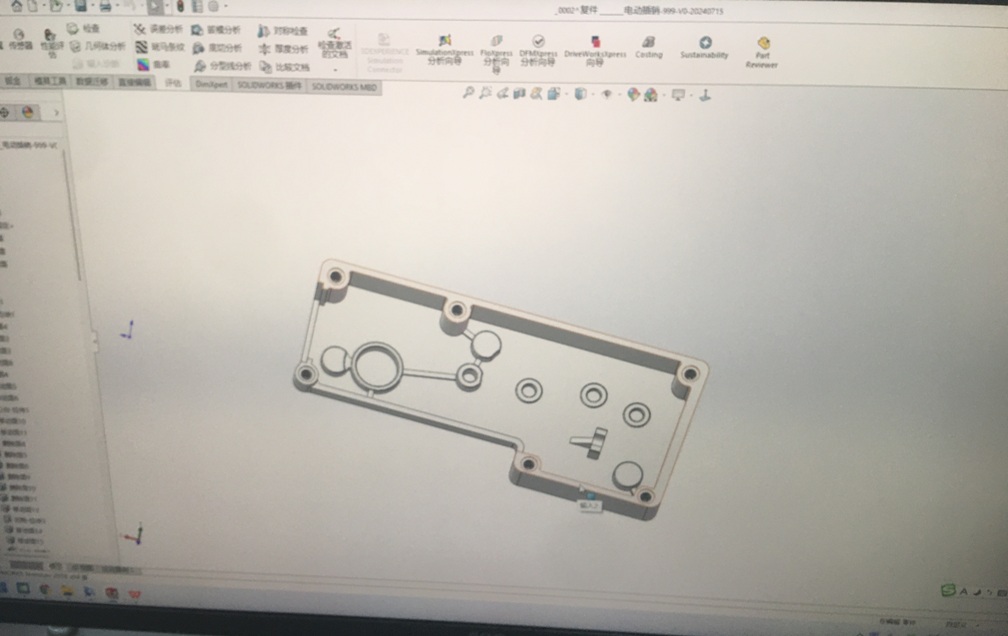
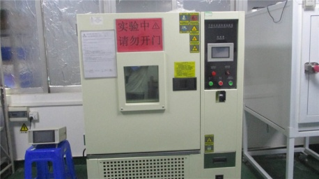
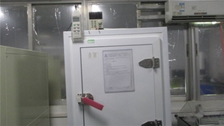
Global Procurement Dynamics & Supply Chain Integration
Procuring brushless DC motors at an industrial scale requires aligning technical specifications with regional supply chain logistics. Procurement officers in Germany, Japan, North America, and Southeast Asia look beyond unit costs. They prioritize long-term component availability, localized technical support, and strict regulatory compliance. Factors such as REACH, RoHS, CE, and UL certifications are critical hurdles that must be cleared prior to manufacturing authorization.
Minimizing the Total Cost of Ownership (TCO)
A low initial purchase price for a BLDC motor can be offset by high field failure rates. Our engineering team addresses this by focusing on winding integrity, bearing quality, and rotor balance. By utilizing automated Swiss gear hobbing and Japanese dynamic balancing equipment, we minimize friction losses and mechanical vibrations. This translates directly to lower energy usage, reduced operating noise, and a longer operational lifespan, reducing overall warranty costs for your brand.
Custom OEM/ODM Workflows
For custom motor designs, we follow a structured engineering workflow:
- Requirement Definition: Assessing application torque, operating voltage, target speed, duty cycle, and mechanical envelope constraints.
- Electromagnetic Simulation: Utilizing software to optimize flux path routing, magnetic material volume, and stator winding density.
- Prototyping & Dynamic Testing: Producing functional prototype samples within 15 to 20 business days for customer evaluation and lab qualification.
- Tooling & Scale Production: Fabricating custom gear molds and winding fixtures for mass production, backed by continuous QA tracking.
Technical & Sourcing Q&A
Answers to common technical questions from application engineers and procurement managers.
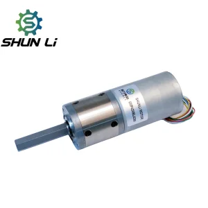
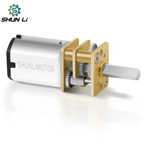
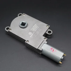
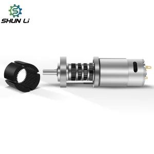
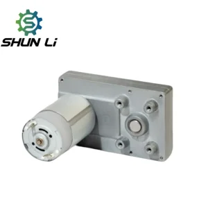
Specialized Gear & Custom DC Motors
Explore our planetary, flat geared, and high-torque custom DC motors designed for robotics, automated lock systems, and precision curtains.