A Three Phase Gear Motor pairs an electric motor with a reduction gearbox to deliver controlled rotation at the load. It is common in conveyors, mixers, pumps, packaging lines, and other equipment requiring steady operation. Inside the motor, three-phase alternating current produces a rotating magnetic field. That field turns the rotor, while the gearbox lowers output speed and increases available torque. The exact result depends on the motor’s speed, gear ratio, and operating conditions.
The energy stakes are substantial. The U.S. Department of Energy’s 2014 Improving Motor and Drive System Performance sourcebook reports that motor-driven systems account for roughly 69% of electricity use in U.S. industry. That figure covers many motor applications, not gear motors alone, but it shows why selection and operating efficiency matter. Small details matter. A conveyor carrying uneven loads may need different starting torque and gearing than a lightly loaded fan. Rated power alone cannot answer that question.
This guide explains the main components, how electrical input becomes geared mechanical output, and which specifications deserve attention. It also considers efficiency, duty cycle, mounting, and common application trade-offs. A gear ratio can increase torque, but it does not create power; friction and heat reduce the usable output. That distinction is easy to overlook. Real installations also face vibration, changing loads, and imperfect maintenance, so catalogue ratings should be checked against the actual machine. The right Three Phase Gear Motor is not simply the largest unit available. It is the one matched to the load, speed, environment, and required service life.
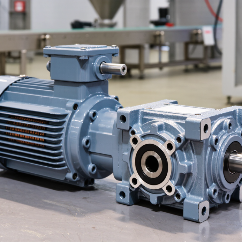
A three-phase gear motor combines an electric motor with a speed-reducing gearbox. It converts electrical energy into controlled mechanical rotation. The three-phase supply creates a rotating magnetic field inside the stator. This field drives the rotor and produces torque. The motor shaft then transfers torque into the gearbox.
The main components include the stator, rotor, motor housing, bearings, and terminal box. The gearbox contains gears, shafts, seals, and lubricant. Gear teeth reduce output speed and increase usable torque.
The output shaft drives equipment such as conveyors, mixers, or lifting systems. A strong housing protects internal parts from dust and vibration. Small details matter.
Tips: Check the rated voltage, frequency, output speed, and torque before installation. Confirm the mounting position and shaft direction. Use suitable lubricant and inspect seals regularly. Listen for unusual noise. Heat can reveal overload, poor alignment, or low lubrication.
A gear motor is not simply a motor with extra gears.
Gear ratio, load pattern, duty cycle, and cooling affect real performance. For example, frequent starts can stress the gearbox more than steady operation. A simplified selection may appear correct but still fail in service.
Measuring current, temperature, and vibration provides more reliable evidence. In practice, maintenance records often expose problems before visible damage appears.
Shamefully, vibration checks are sometimes skipped. That is worth reconsidering.
What Is a Three Phase Gear Motor and How Does It Work?
A three-phase gear motor combines an induction motor with a gearbox. Its rotation begins with three alternating currents, spaced 120 electrical degrees apart. These currents enter separate stator windings and create a rotating magnetic field inside the motor.
That field moves smoothly, rather than pulsing like single-phase power. The rotor follows the field because electromagnetic forces induce current in its conductive bars. It must rotate slightly slower than the magnetic field. This small difference, called slip, produces useful torque. Reverse any two supply phases, and the rotating field changes direction. A qualified technician should verify this with proper test equipment.
The gearbox then reduces the motor’s high speed and increases output torque. For example, a motor may spin near 1,500 revolutions per minute, while the geared shaft turns much slower. The teeth inside the gearbox transfer force through several stages, often using oil or grease to control friction and heat. In real installations, voltage imbalance, poor alignment, or insufficient lubrication can reduce efficiency. I have found that sound and temperature reveal problems early, although they should never replace electrical testing. The ideal theory looks clean. Workshop conditions are not. Load changes, starting torque, and gear wear can alter the result. Checking current on all three phases gives a more reliable picture of operation.
| Component or Stage | How It Works | Typical or Illustrative Data | Effect on the Output |
|---|---|---|---|
| Three-phase supply | Three alternating voltages are separated by 120 electrical degrees. Connected to the motor windings, they create a rotating magnetic field. | Common supply frequencies include 50 Hz and 60 Hz. Supply voltage varies by region and motor rating. | Provides the electrical input that drives the motor; the correct rated voltage and frequency are required. |
| Stator windings | Windings arranged around the stationary motor core carry the three phase currents and produce the rotating magnetic field. | The field’s synchronous speed depends on supply frequency and the number of motor poles. | Sets the motor’s basic rotating-field speed and direction. |
| Rotor and induction | The rotating field induces current in the rotor. Interaction between that current and the magnetic field produces torque, turning the rotor. | In an induction motor, the rotor normally turns slightly slower than synchronous speed; this difference is called slip. | Converts electrical energy into mechanical rotation and torque. |
| Synchronous speed reference | The theoretical rotating-field speed is calculated from supply frequency and pole count: speed in rpm = 120 × frequency in Hz ÷ number of poles. | At 50 Hz: 2-pole = 3,000 rpm; 4-pole = 1,500 rpm; 6-pole = 1,000 rpm. At 60 Hz: 2-pole = 3,600 rpm; 4-pole = 1,800 rpm; 6-pole = 1,200 rpm. | Actual induction-motor rotor speed is lower under load because of slip. |
| Gearbox | Gears reduce motor speed and increase available output torque, allowing the motor to suit a slower, higher-torque application. | For an illustrative 10:1 reduction, output speed is approximately one-tenth of motor speed before accounting for slip and other operating factors. | Changes the speed and torque delivered to the driven equipment. Gearbox efficiency and load affect actual performance. |
| Gear motor output | The motor shaft drives the gearbox, whose output shaft transmits rotation to machinery such as a conveyor or mixer. | Approximate output speed = motor shaft speed ÷ gear reduction ratio. | Provides a compact drive with motor rotation adjusted to the application’s speed and torque needs. |
| Direction of rotation | Changing the order of any two supply phases reverses the direction of the rotating magnetic field in a typical three-phase motor. | Direction should be checked safely and in accordance with the motor and equipment instructions. | Reverses motor rotation and, in turn, gearbox output rotation. |
A three-phase gear motor combines an electric motor with a mechanical gearbox. The motor creates a rotating magnetic field from three alternating electrical phases. The gearbox then reshapes that motion for the machine’s actual needs. It is the practical link between fast rotation and controlled movement.
Gear ratio is the main speed control. A reduction gearbox turns a high-speed motor shaft into slower output rotation. In return, the output shaft produces greater torque. For example, a 20:1 ratio can reduce speed significantly while multiplying available torque, although friction causes some power loss. Higher ratios are not automatically better. They may increase heat, backlash, and starting stress.
Direction depends on the gear arrangement and electrical phase sequence. Reversing any two motor phases usually changes the motor’s rotation direction. A gearbox can also reverse output direction when its internal gear layout requires it. During commissioning, technicians check rotation with a brief test pulse. This simple step can prevent damage to conveyors, pumps, or threaded mechanisms. Load behavior matters too. A motor may reach its rated speed without handling sudden torque demand. Gear teeth, bearings, lubricant, and alignment all influence reliable operation. In practice, choosing a ratio from speed alone is incomplete. I would also question acceleration, duty cycle, noise, and available stopping control before approving the design.
A three-phase gear motor combines a three-phase induction motor with a gearbox. The motor creates a rotating magnetic field from three offset currents. The gearbox then reduces speed and increases shaft torque.
Helical gear motors suit conveyors and mixers because they run quietly and efficiently. Bevel gear motors transfer power through a 90-degree direction change. Worm gear motors offer compact reduction and strong holding performance, but they usually lose more energy as heat. Planetary gear motors provide high torque in a small housing.
Operating features depend on the load, duty cycle, and reduction ratio. A properly sized motor delivers smoother torque than many single-phase systems. It also handles frequent industrial operation more reliably.
The U.S. Department of Energy reports that motor-driven equipment can consume over 70% of industrial electricity in some facilities. The International Energy Agency estimates motor systems use roughly half of global electricity. These figures make efficiency more than a specification. It becomes an operating cost issue.
However, real installations are less tidy; poor alignment, oversized motors, and blocked cooling paths can erase expected savings.
Tips: Check rated torque, output speed, service factor, insulation class, and enclosure rating together. Match the gearbox to shock loads, not only average loads. An inverter can improve speed control, but it may require suitable bearings and thermal checks. Review measured temperature and vibration after installation. Paper calculations can miss real dust, starts, and mechanical friction.
A three phase gear motor combines a three phase induction motor with a gearbox. The motor creates steady rotational force, while the gearbox reduces speed and increases output torque. This arrangement suits machines that need controlled movement for long operating periods.
In factories, these motors drive conveyor belts, screw feeders, mixers, pumps, packaging lines, and automated doors. A conveyor moving heavy cartons may need low speed and high starting torque. A mixer may require stronger shock resistance because its load changes during operation. Dust, moisture, heat, and frequent starts also influence the motor’s suitability. Washdown areas need appropriate enclosure protection. Poor protection can cause early bearing or insulation failure.
Selection should begin with output speed, required torque, duty cycle, and available voltage. Check the gearbox ratio, mounting position, shaft dimensions, and service factor. A motor that appears powerful enough may still stall during startup. I have seen equipment fail because engineers considered running torque but ignored acceleration torque. That mistake is expensive.
Measure the real load when possible. Manufacturer data can help, but field conditions often differ from catalog assumptions. Efficiency matters during long shifts, yet a smaller motor is not always better. Thermal limits, braking needs, noise, maintenance access, and replacement availability deserve equal attention. Leave some capacity for unexpected loads. Not too much, though. Oversizing may increase purchase cost, energy use, and mechanical stress.
It combines an electric motor and gearbox. The motor creates rotation, while the gearbox reduces speed and increases usable torque.
Check bearings, seals, lubricant, and the output shaft. Listen for unusual noise and look for heat, dust buildup, or vibration.
Helical units run quietly, while bevel units change power direction by 90 degrees. Worm units are compact but can lose more energy as heat. Planetary units deliver high torque in a small housing.
Confirm rated voltage, frequency, output speed, and torque. Also verify mounting position and shaft direction. Small mismatches matter.
Match the output torque and speed to the load, duty cycle, and reduction ratio. Consider shock loads, not only average loads.
Yes. Repeated starts can stress the gearbox more than steady operation. The difference may not be obvious at first.
Rising temperature, unusual noise, or increased vibration can suggest overload, poor alignment, or low lubrication. Measure and record them; guessing is not enough.
An inverter can provide speed control. Check whether the motor has suitable bearings and adequate cooling for the planned operation.
Poor alignment, oversized motors, blocked cooling paths, dust, and friction can reduce efficiency. Actual site conditions deserve a closer look.
A Three Phase Gear Motor combines a three-phase electric motor with a mechanical gearbox to deliver controlled rotational power. The motor converts three-phase electrical energy into a rotating magnetic field, which drives the rotor and creates continuous motion. Compared with single-phase designs, this arrangement generally provides smoother operation, reliable starting performance, and efficient power delivery for demanding equipment.
The attached gearbox adjusts the motor’s output by reducing speed and increasing torque, while different gear arrangements can support various rotation directions and operating requirements. Common types include helical, bevel, worm, and planetary geared motors, each offering distinct advantages in efficiency, compactness, noise level, and load handling. These motors are widely used in conveyors, mixers, pumps, material-handling systems, packaging equipment, and automated machinery. When selecting one, users should consider power rating, output speed, required torque, duty cycle, installation space, environmental conditions, maintenance needs, and compatibility with the driven machine.

DC Motor B2B