 DC Motor B2B
Osaka Market Featured Flagship Series
Premium micro-geared DC motor configurations specifically optimized for Kansai lock manufacturing ecosystems, offering minimal footprint and peak torque performance.
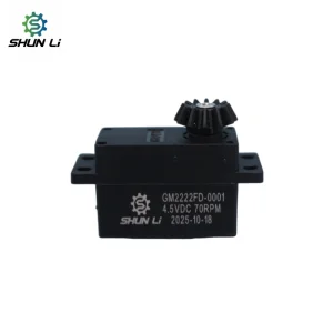
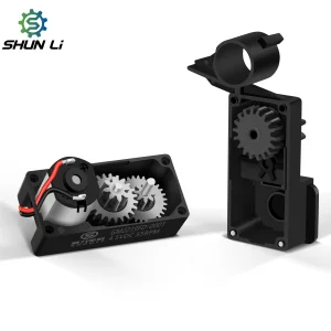
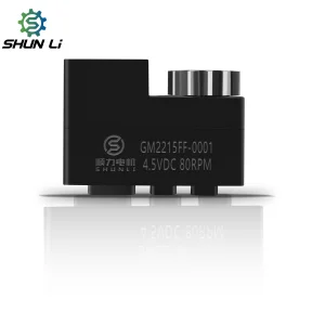
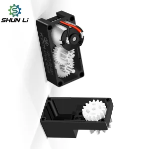
Osaka's Industrial Ecosystem & The Smart Lock Paradigm Shift
Osaka, long recognized as the heart of Japan's mechanical lock fabrication and precision metalworking industries (with manufacturing hotspots extending across Higashiosaka and Sakai), is currently undergoing a massive transformation. As smart buildings, luxury residential developments in Umeda and Namba, and unmanned hotels emerge, the traditional mechanical deadbolt is being replaced by IoT-enabled electro-mechanical access portals. This shift demands high-reliability micro-motors that can fit within existing Japanese lock mortise configurations without structural modification.
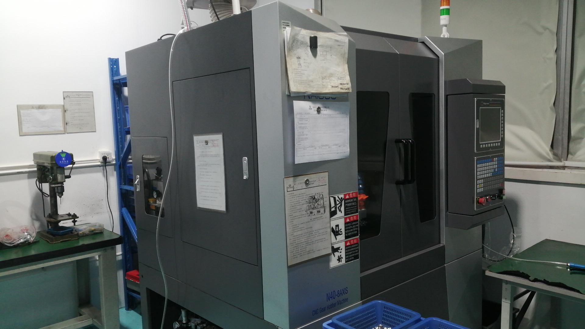
For lock factories operating within the Osaka market, the design margins are exceptionally tight. Space restrictions are dictated by standard doors, requiring motors that measure less than 12mm in diameter yet deliver over 3 kg.cm of stall torque. Furthermore, the noise constraints in Japanese multi-family apartments are incredibly strict. Motors must operate quietly (under 38 decibels) and exhibit dynamic efficiency to prolong battery changes past 24 months. Our factory utilizes Swiss-style automated hobbing and Japanese-grade micro-balancing machines to satisfy these strict conditions, supplying micro-drives directly to security manufacturers in Kansai.
Why Osaka Factories Choose DQC Motors
- Absolute Space Optimization: Standardized housing models for Japanese lock mortises.
- Acoustic Attenuation: Low sound profile via custom helical gear patterns and dynamic rotor balancing.
- Under 3V to 12V Operation: Designed to maintain peak performance even on depleted battery cells.
- Zero-Backlash Engineering: Eliminates backlash to prevent lock jams and misalignment.
- JIS Conformity: All motors meet Japanese Industrial Standards for physical tolerances and electrical interference.
Global Smart Lock Motor Technical Roadmap
A detailed examination of operational metrics and design constraints across high-precision electronic lock designs globally.
Globally, the electronic lock sector is divided between high-traffic commercial building locks (running on 12V DC power lines) and residential battery-powered smart deadbolts (operating at 3V, 4.5V, or 6V). In both cases, the micro-motor serves as the central point of mechanical movement. Low-quality copper windings or inaccurate gear alignment can lead to thermal stress, high friction, and premature wear, resulting in lock failure. The table below represents the core technical metrics designed to protect against lock failure under standard operating profiles:
| Specification Metric | 3V-4.5V Micro Geared Series | 6V High-Torque Series | 12V Commercial Series | Osaka Standard Compliance |
|---|---|---|---|---|
| Rated Torque range | 1.2 - 2.0 kg.cm | 2.0 - 3.2 kg.cm | 3.5 - 5.0 kg.cm | Meets JIS High-Load Level 1 |
| Operational Voltage | 2.4V - 5.0V DC | 4.5V - 7.2V DC | 9.0V - 14.5V DC | Stabilized against voltage drops |
| No-load Current | < 60 mA | < 85 mA | < 120 mA | Minimizes standby battery drain |
| Noise Target (10cm) | ≤ 35 dB | ≤ 38 dB | ≤ 42 dB | Acoustically optimized |
| Gear Material | Carbon steel / Sintered alloy | Hardened Steel / Brass | Tempered Carbon Steel | High wear resistance |
| Life Cycle Rating | 200,000 Cycles | 300,000 Cycles | 500,000 Cycles | Designed for long durability |
ABOUT DQC: Packing Massive Torque Into Miniature Spaces
Inside a premium robotic joint, an automated medical pump, or a high-end smart lock, space is the ultimate luxury. At DQC, we measure our success in micrometers and decibels.
Our mission is to take advanced, heavy-duty rotational power and compress it into the most compact, energy-efficient footprints imaginable. Our expertise lies in the micro-details of motion. From precision-wound copper rotors and high-purity commutators to zero-backlash planetary gear trains, every single internal component of a DQC motor is optimized to eliminate friction and maximize heat dissipation.
By combining advanced automated Swiss-style hobbing with Japanese dynamic balancing, we ensure our micro drives deliver the fluid, whispering-quiet power your brand promises. When your next high-tech innovation relies on repeated mechanical perfection, let DQC be the core that spins it forward.
Production Processes & Traceability

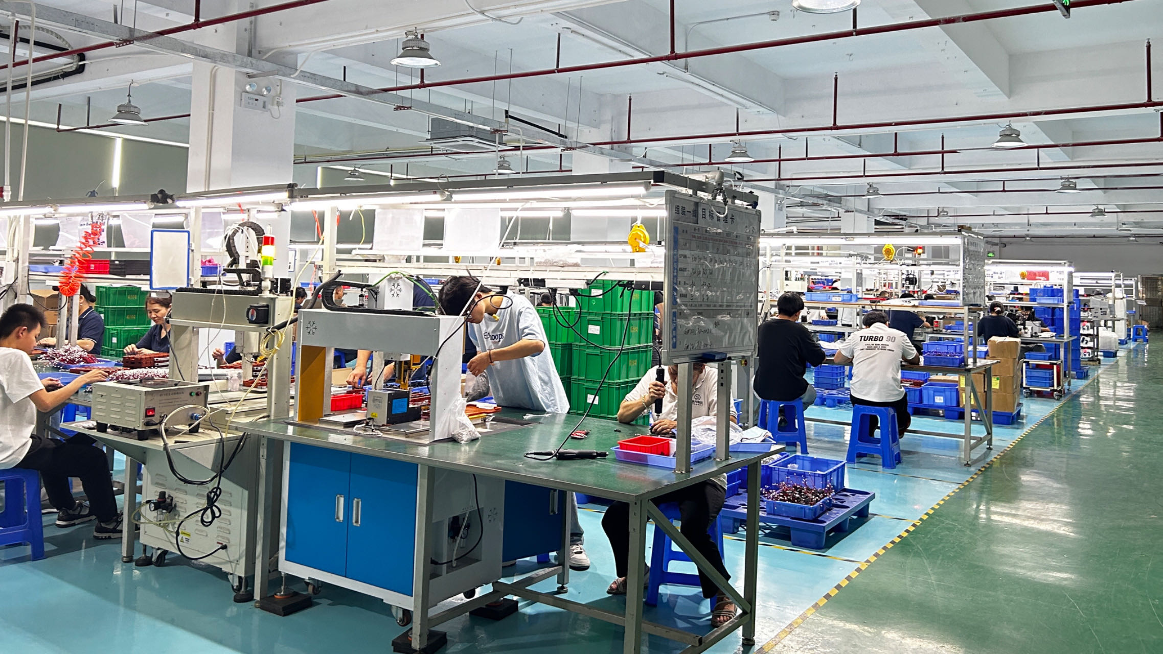
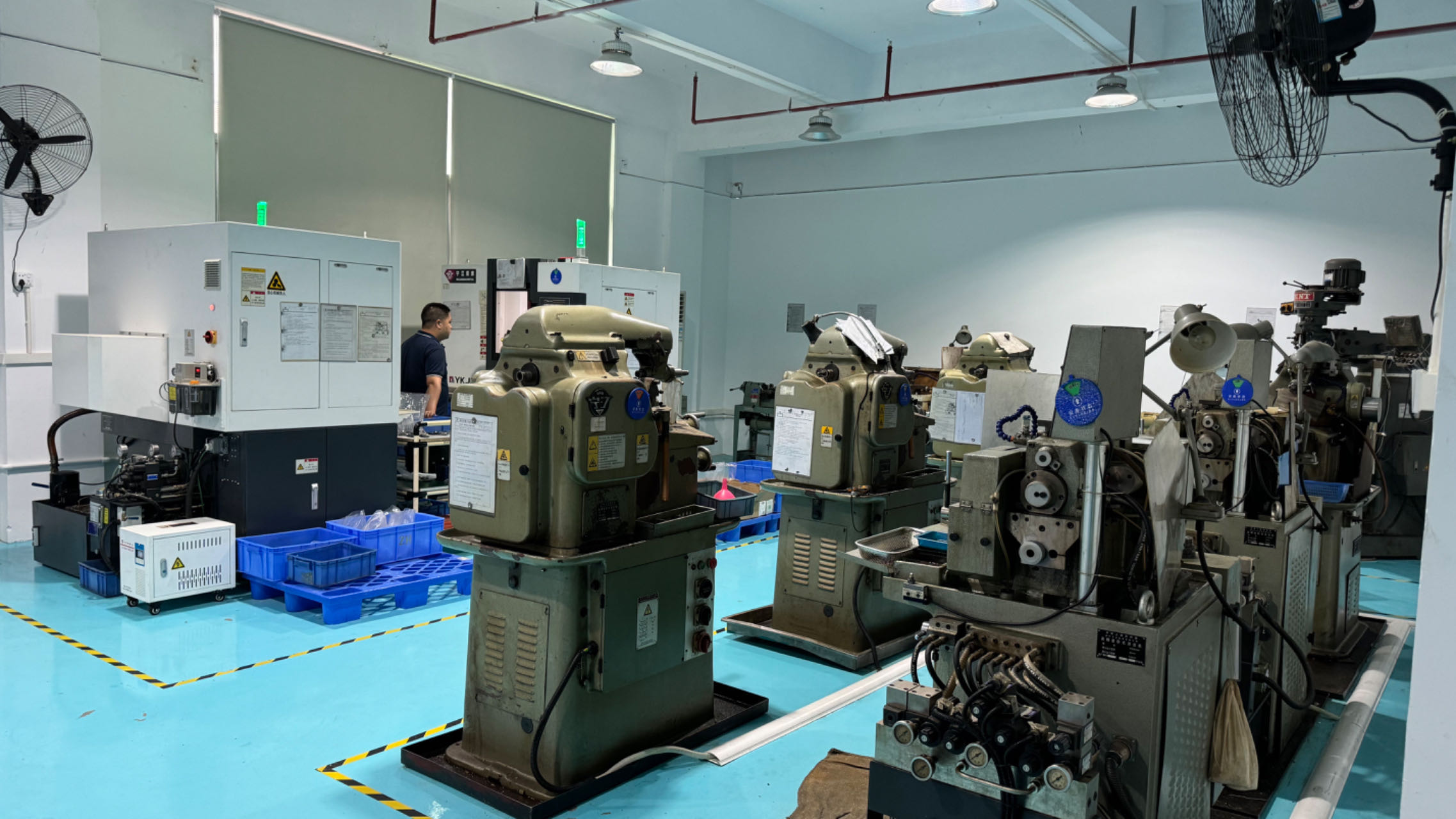
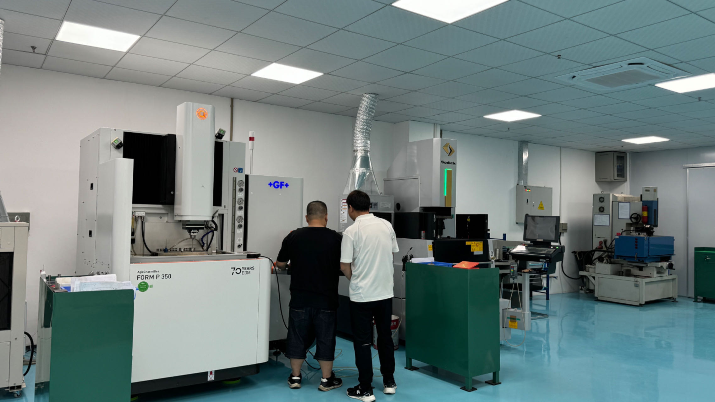
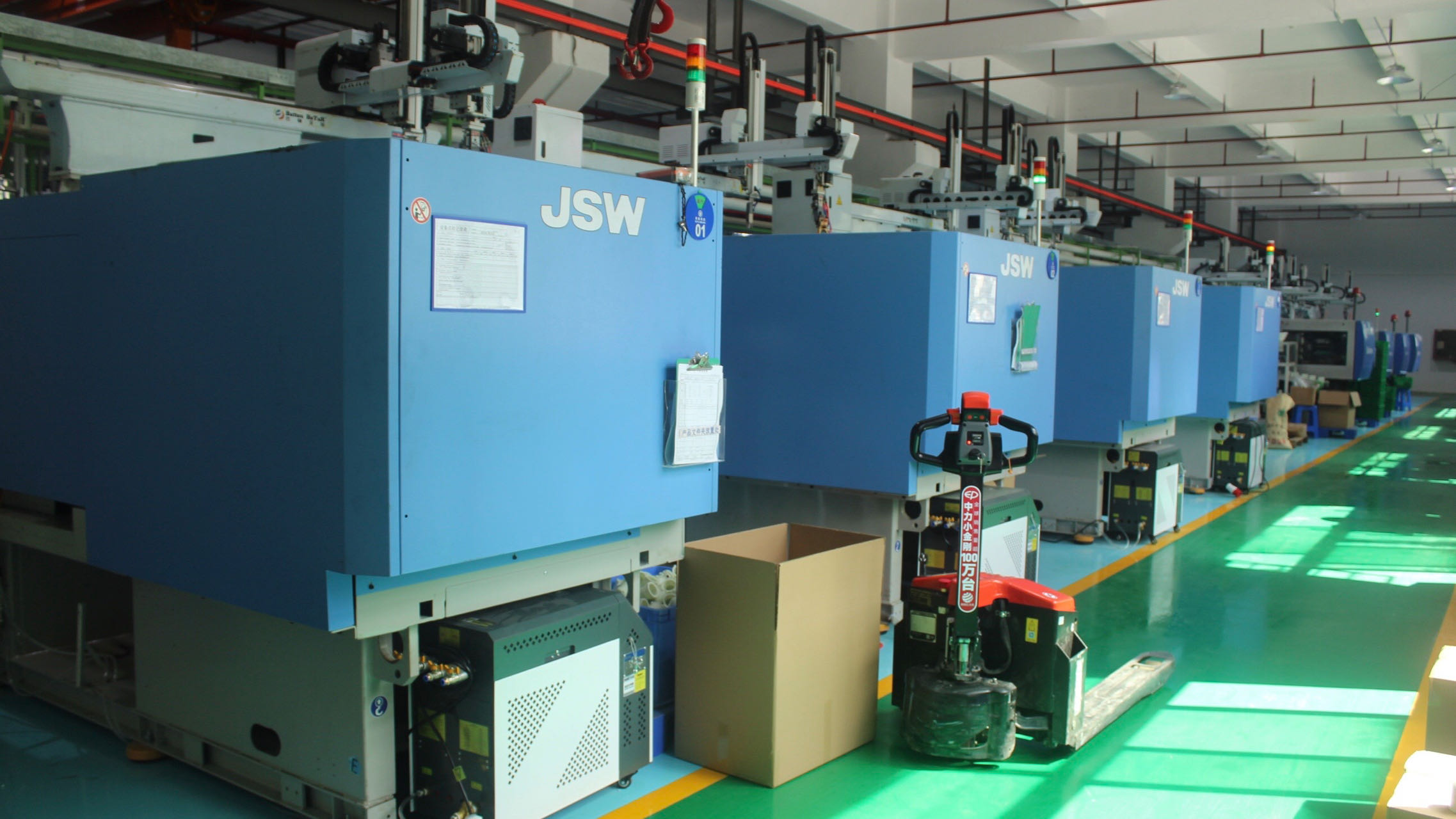
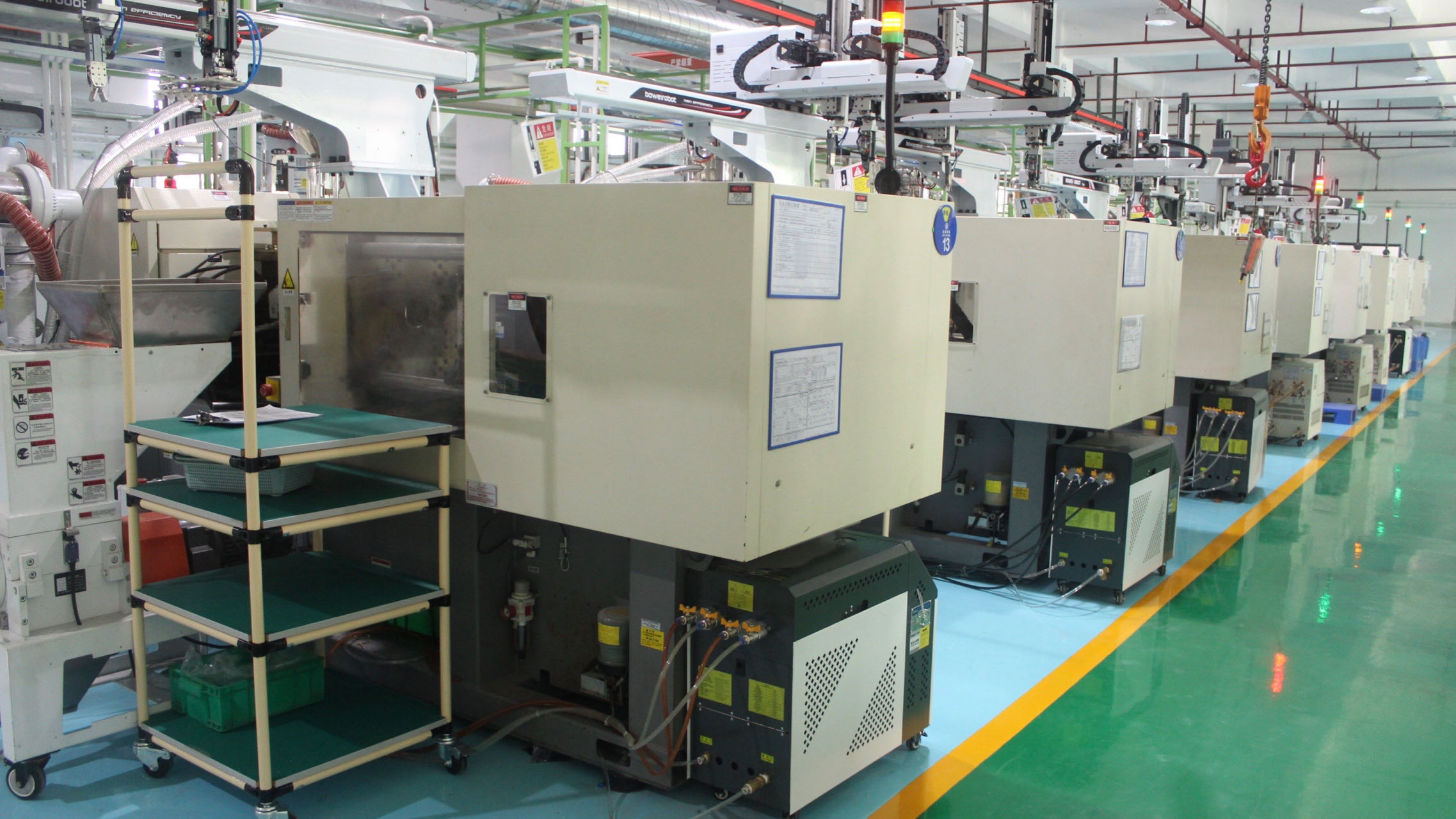
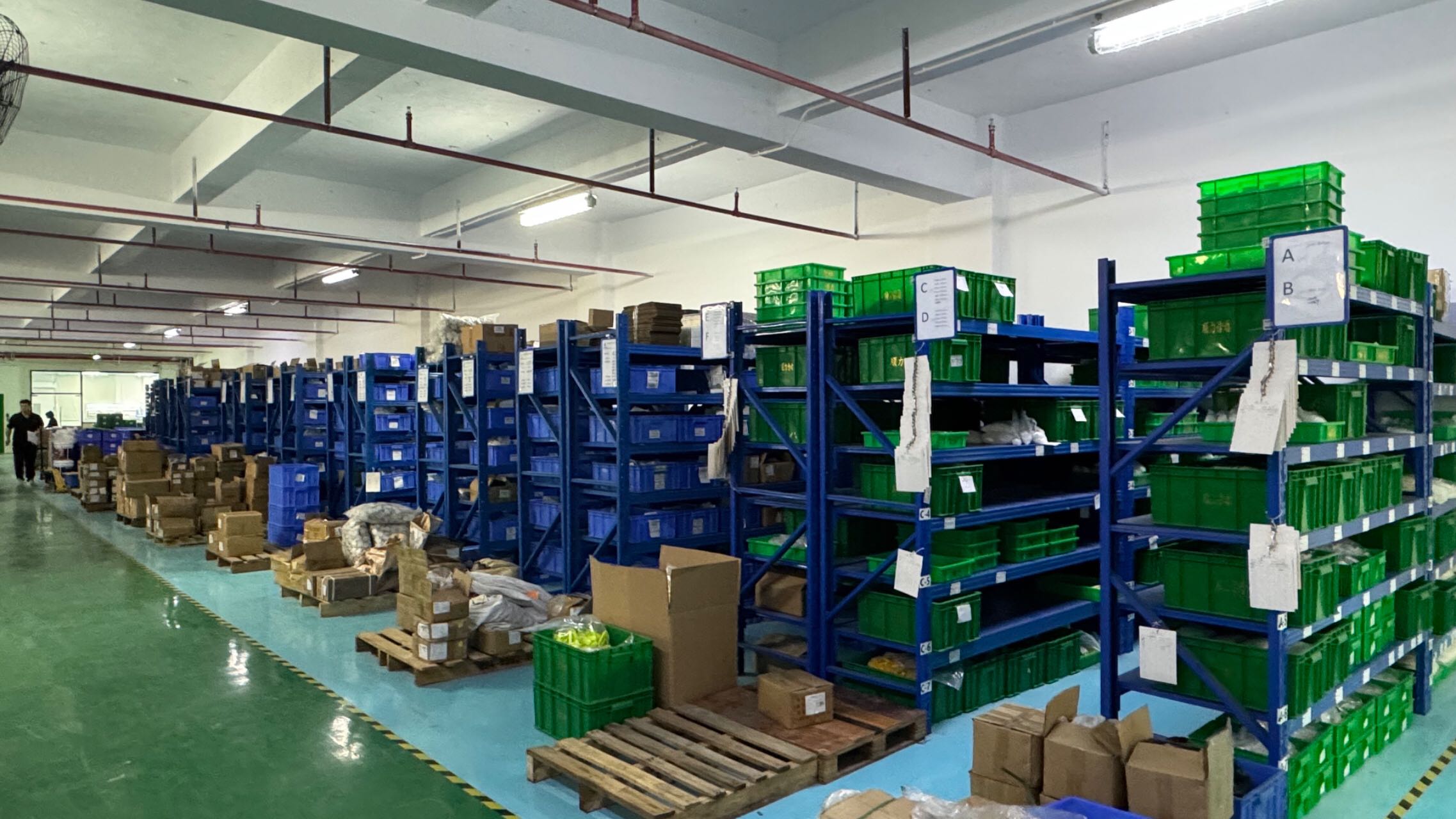
DQC Integrated Smart Manufacturing Complex (Assembly, CNC Machining, and Global Quality Assurance Hub)
Production Flow & Cleanroom Operations

Chemical composition analysis and precision thickness evaluation.
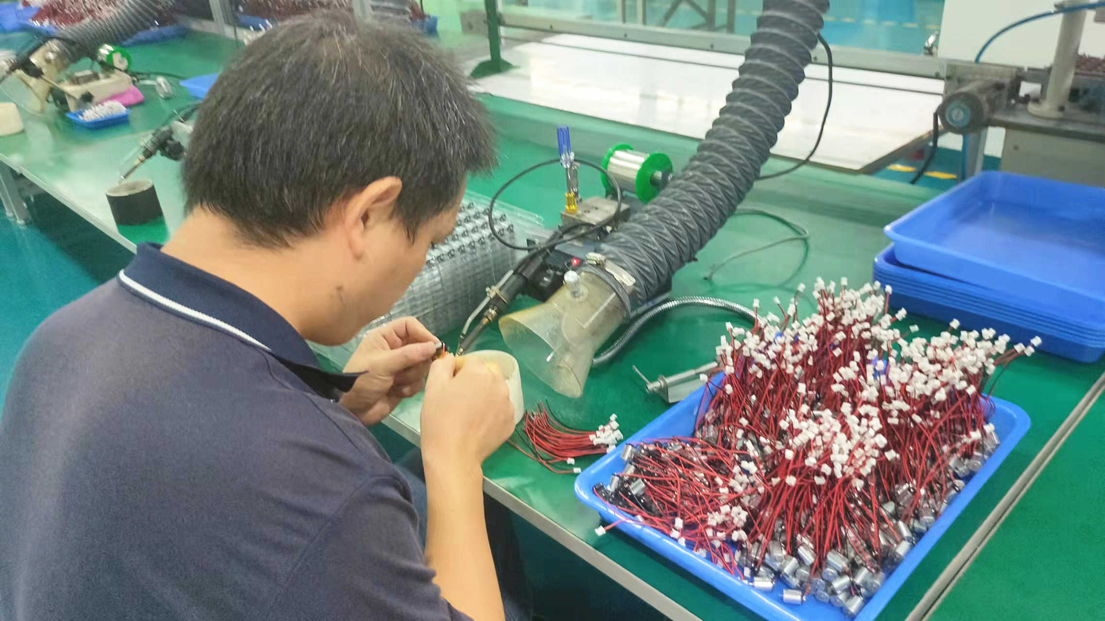
Clean contact connection with precise lead-free temperature control.
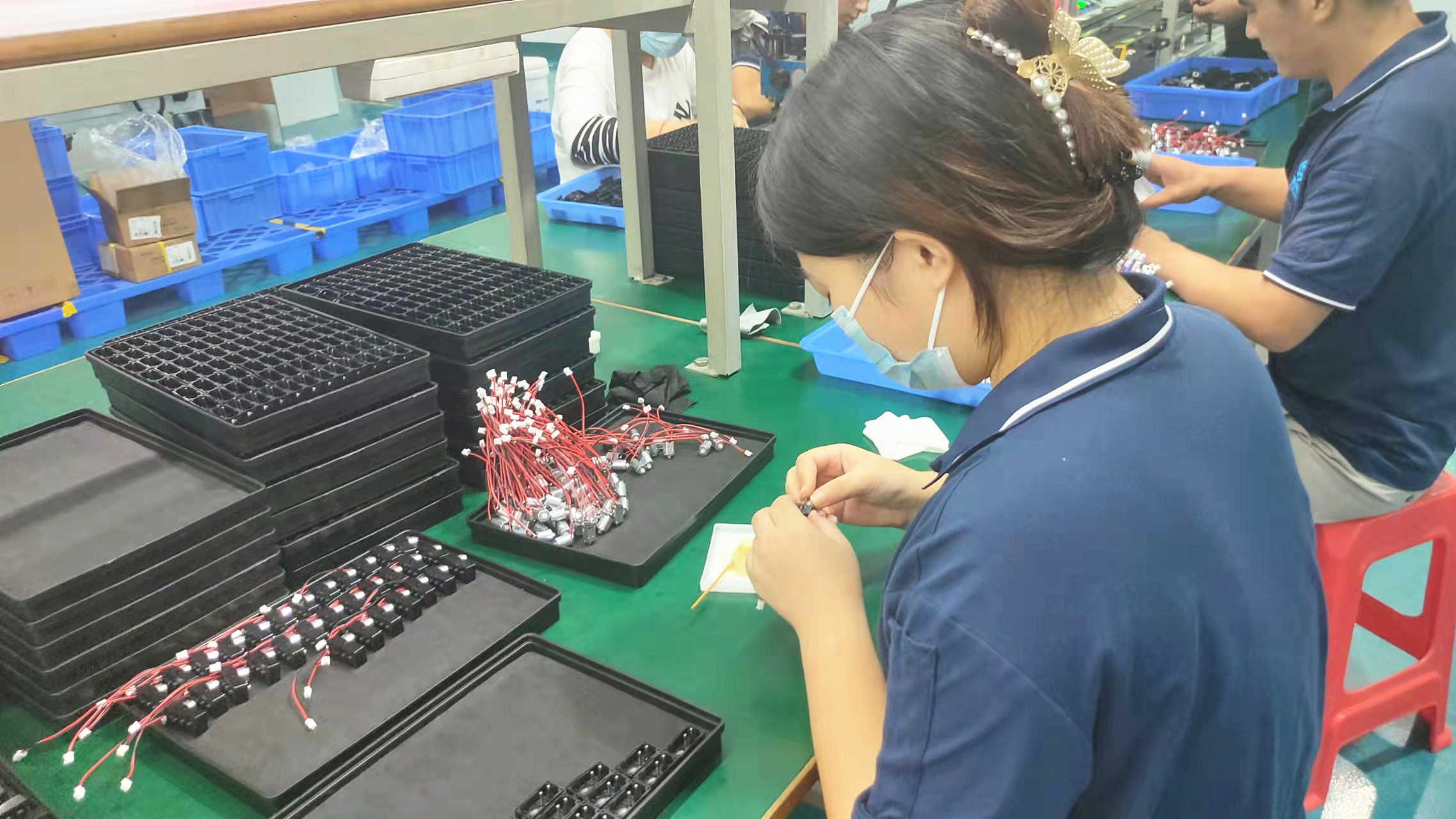
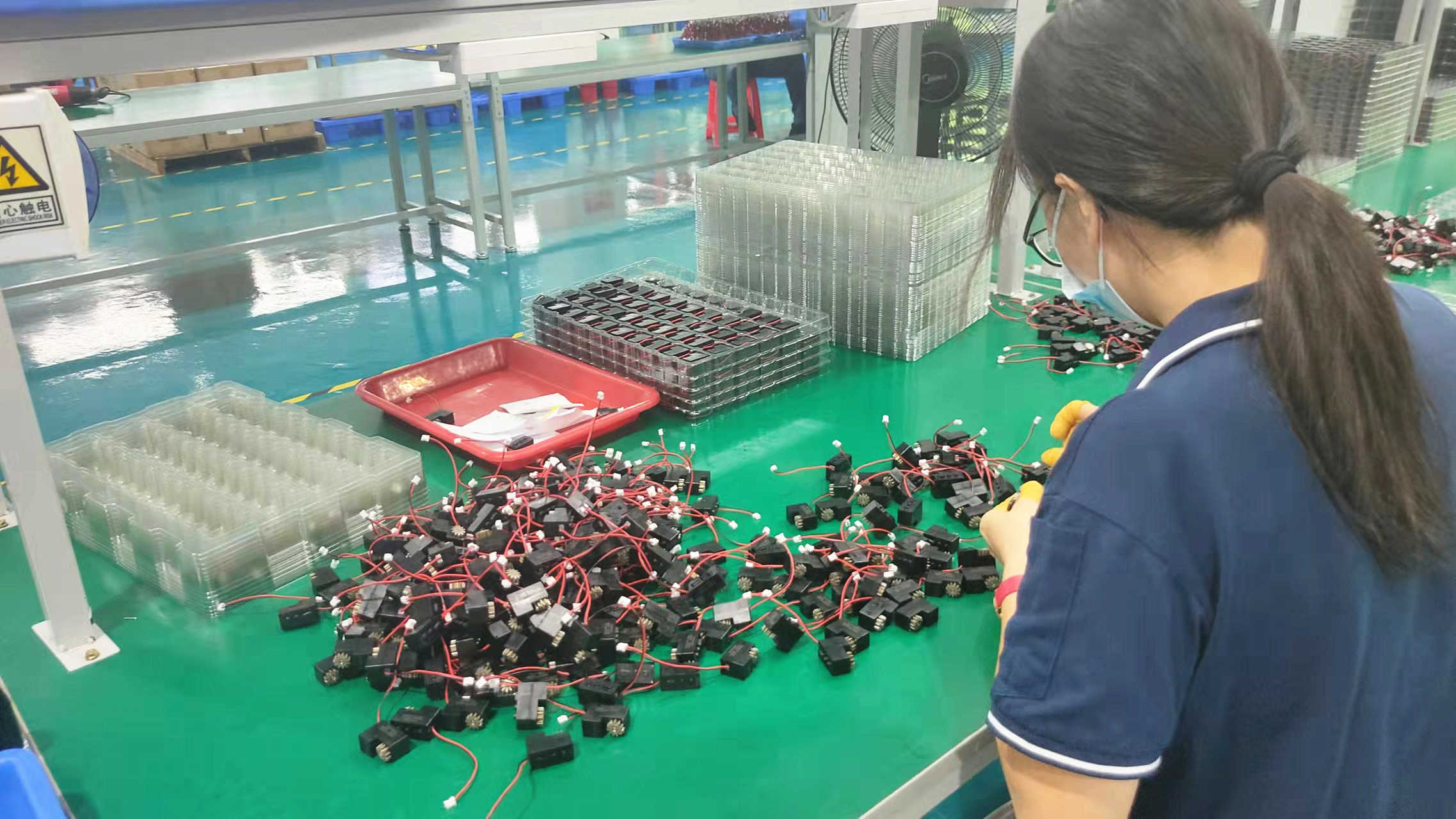
Strict environment assembly for gear alignment stability.
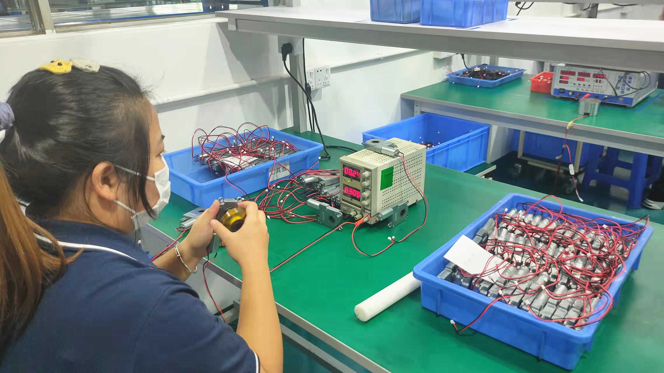
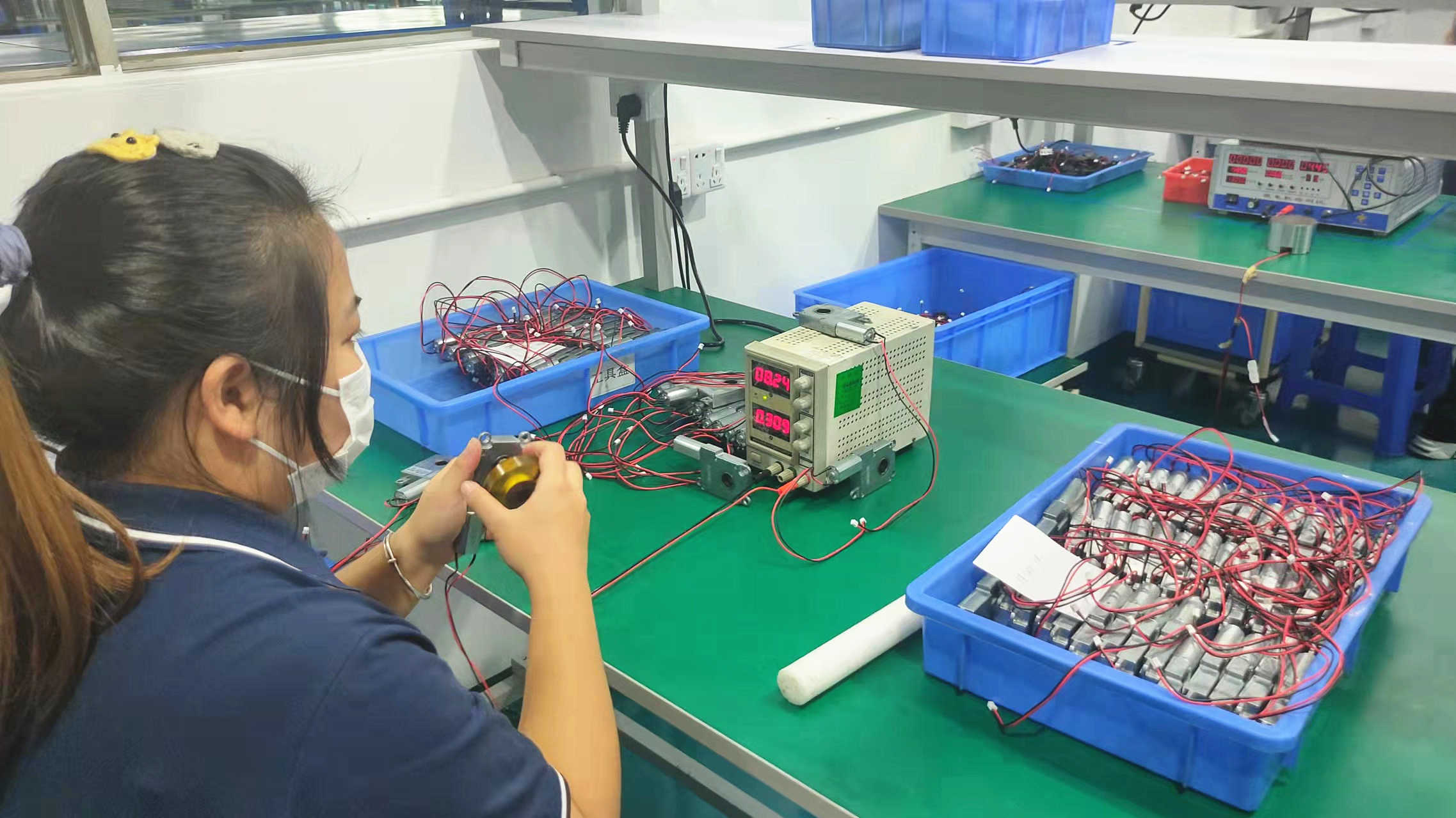
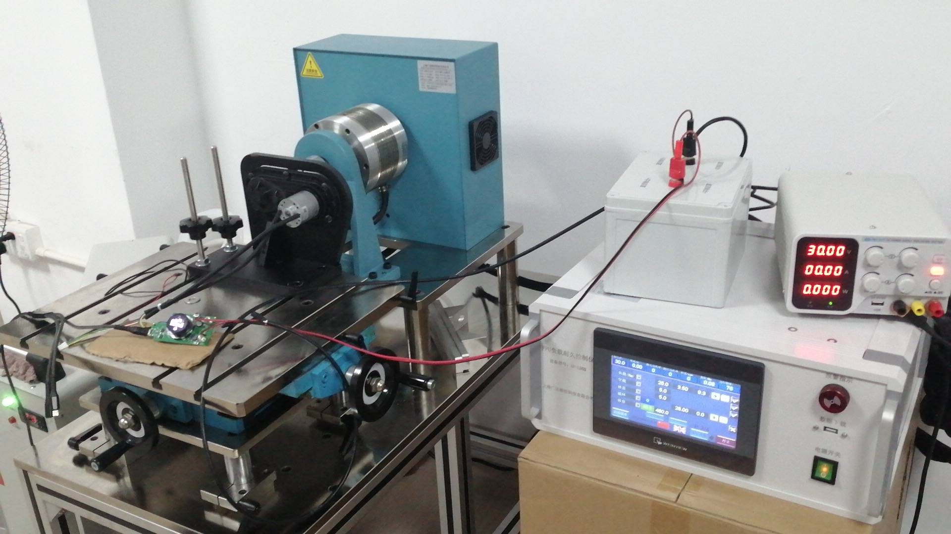
Dynamic verification of torque curves and current drawing metrics.
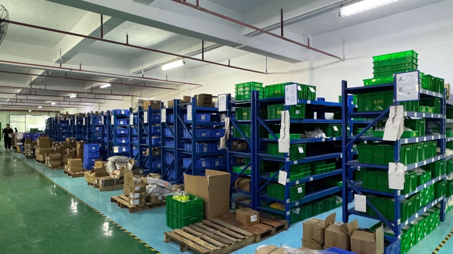
Protective tray arrangement designed for fast automated handling.
Maintains motor integrity against humidity and oxidation before shipping.
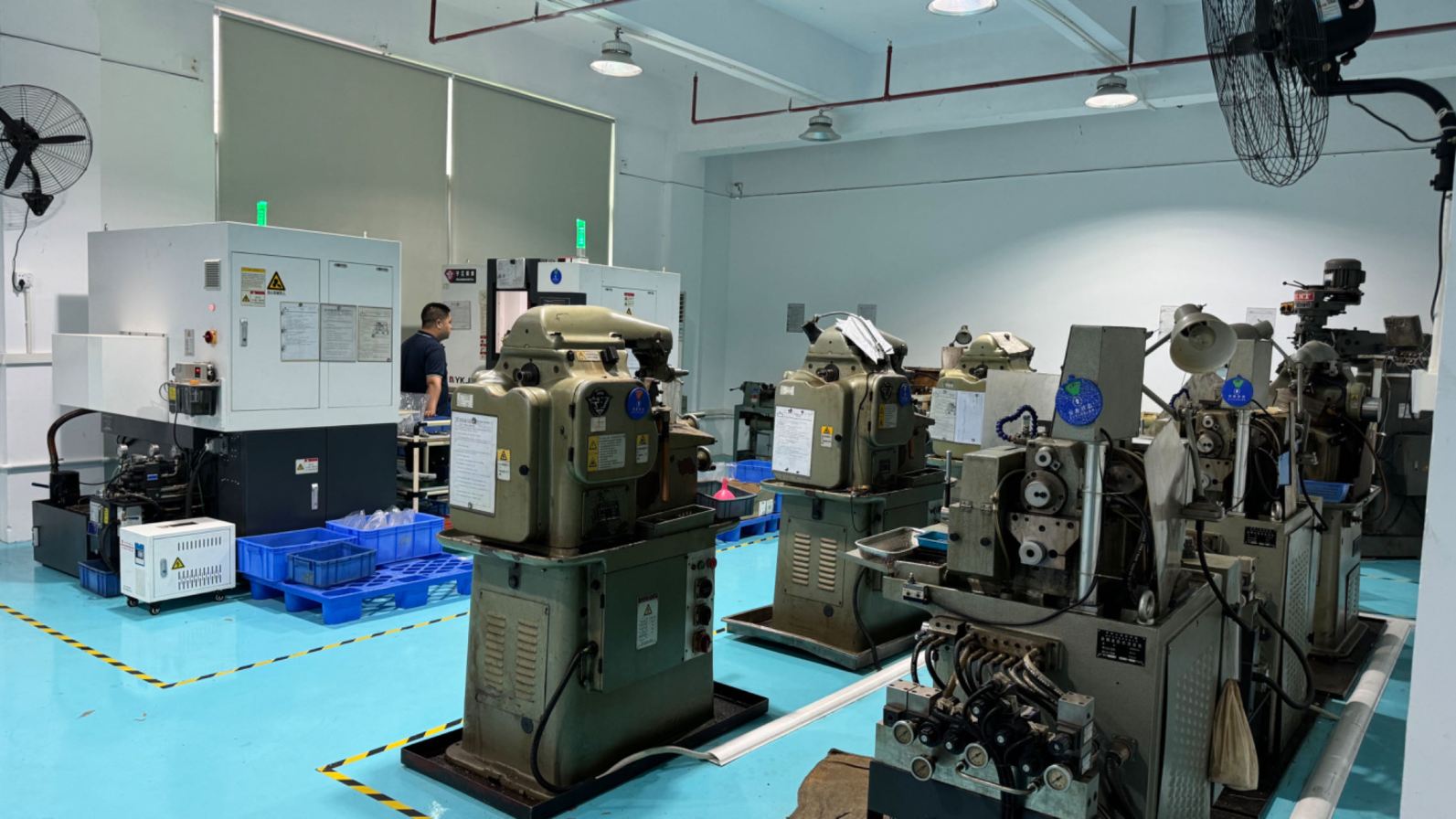
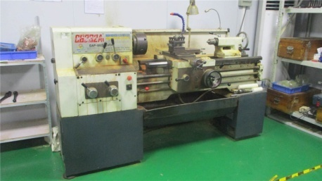
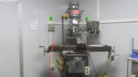
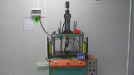
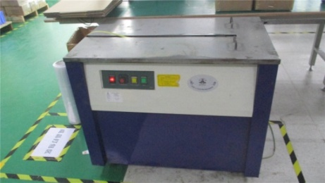
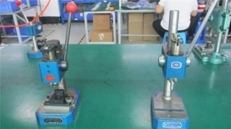
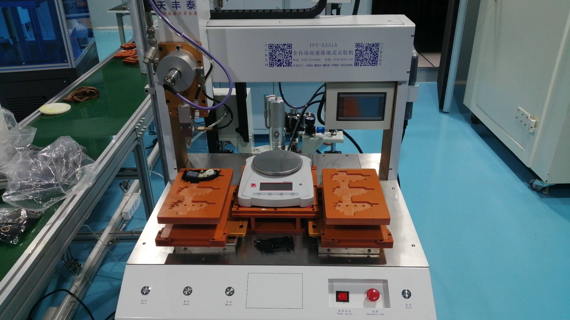
Advanced Machinery & Tooling Assets
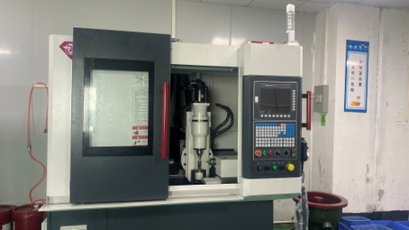
Our production floor uses precision CNC systems to achieve tolerances within the micrometer range.
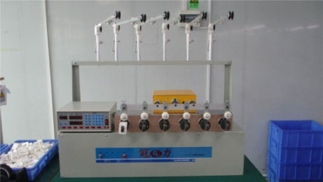
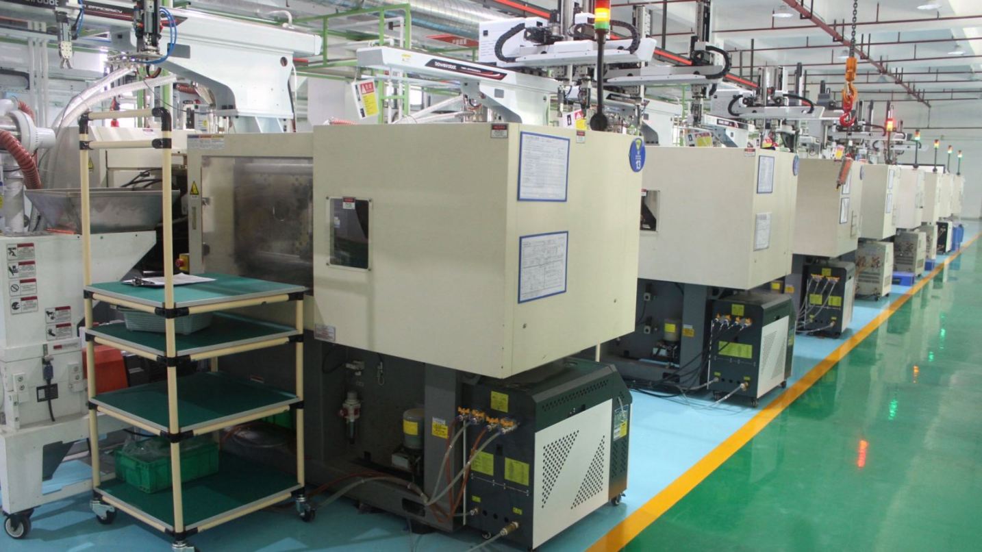
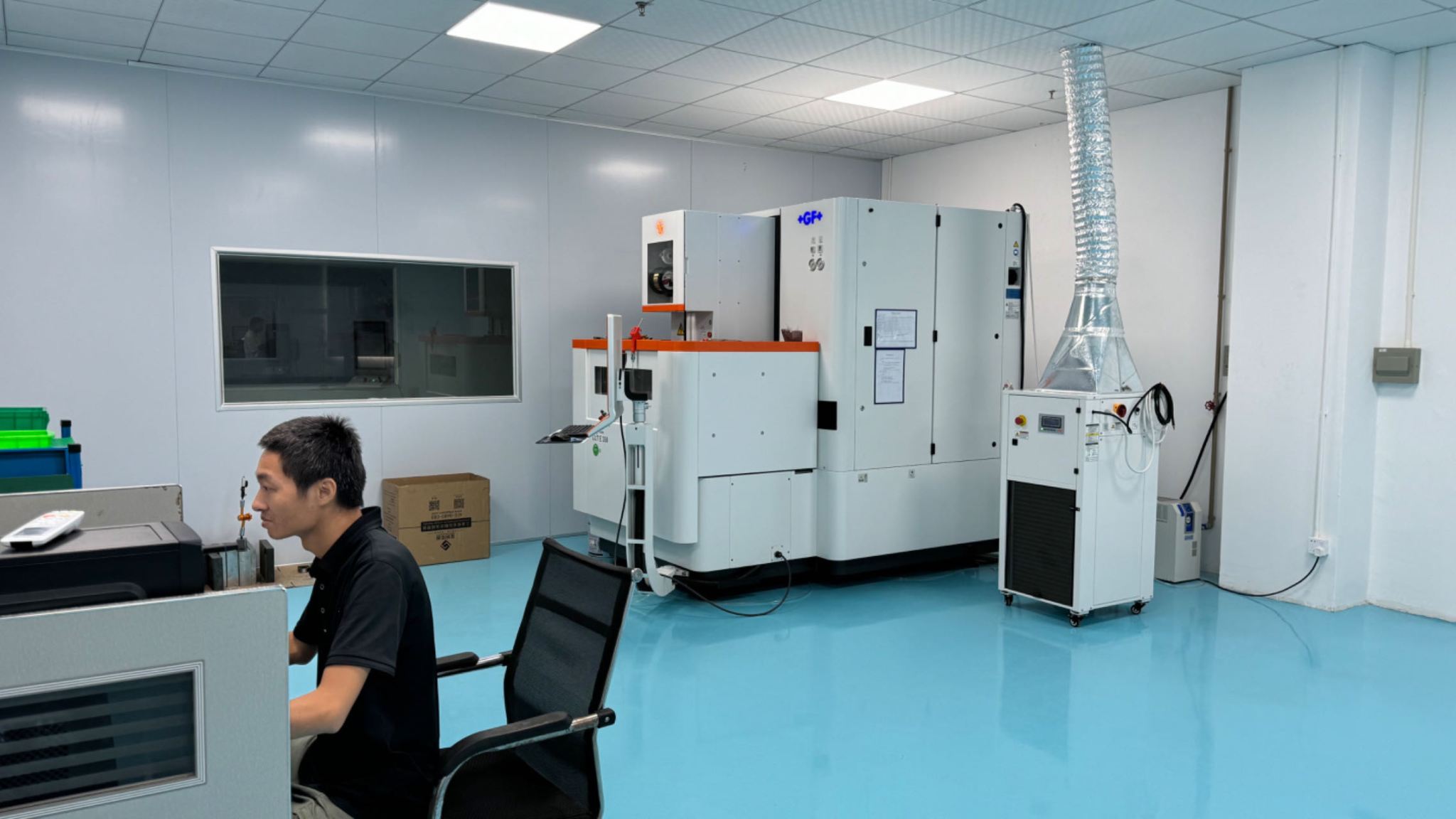
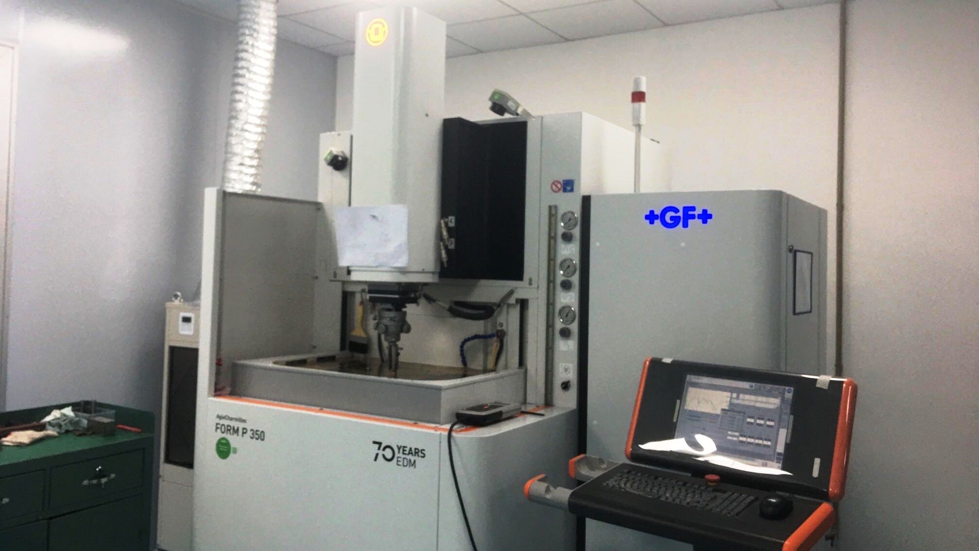
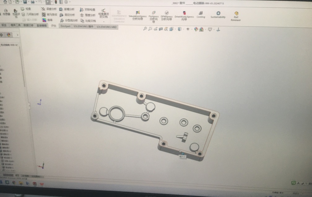
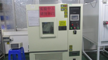
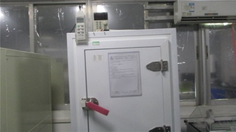
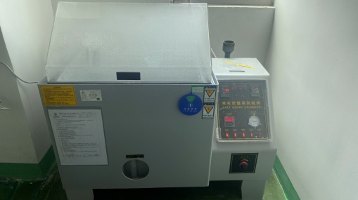
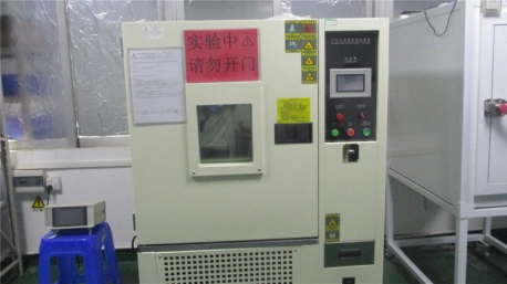
Quality Control Lab & Environmental Performance Verification
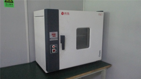
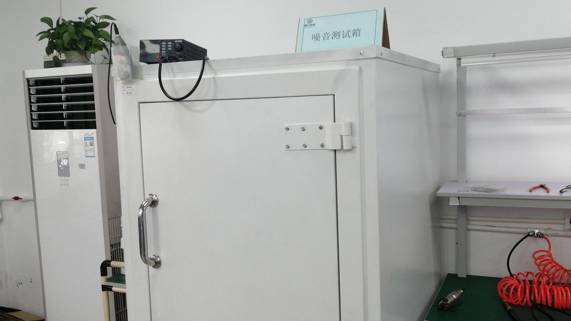
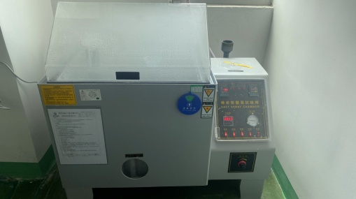
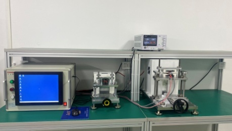
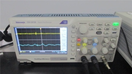
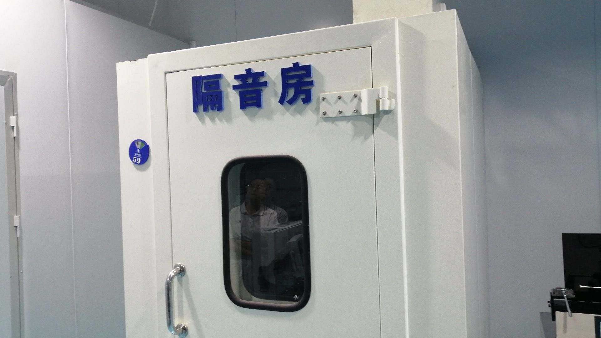
Before leaving the facility, each batch is tested under extreme thermal, acoustic, and mechanical stress profiles.
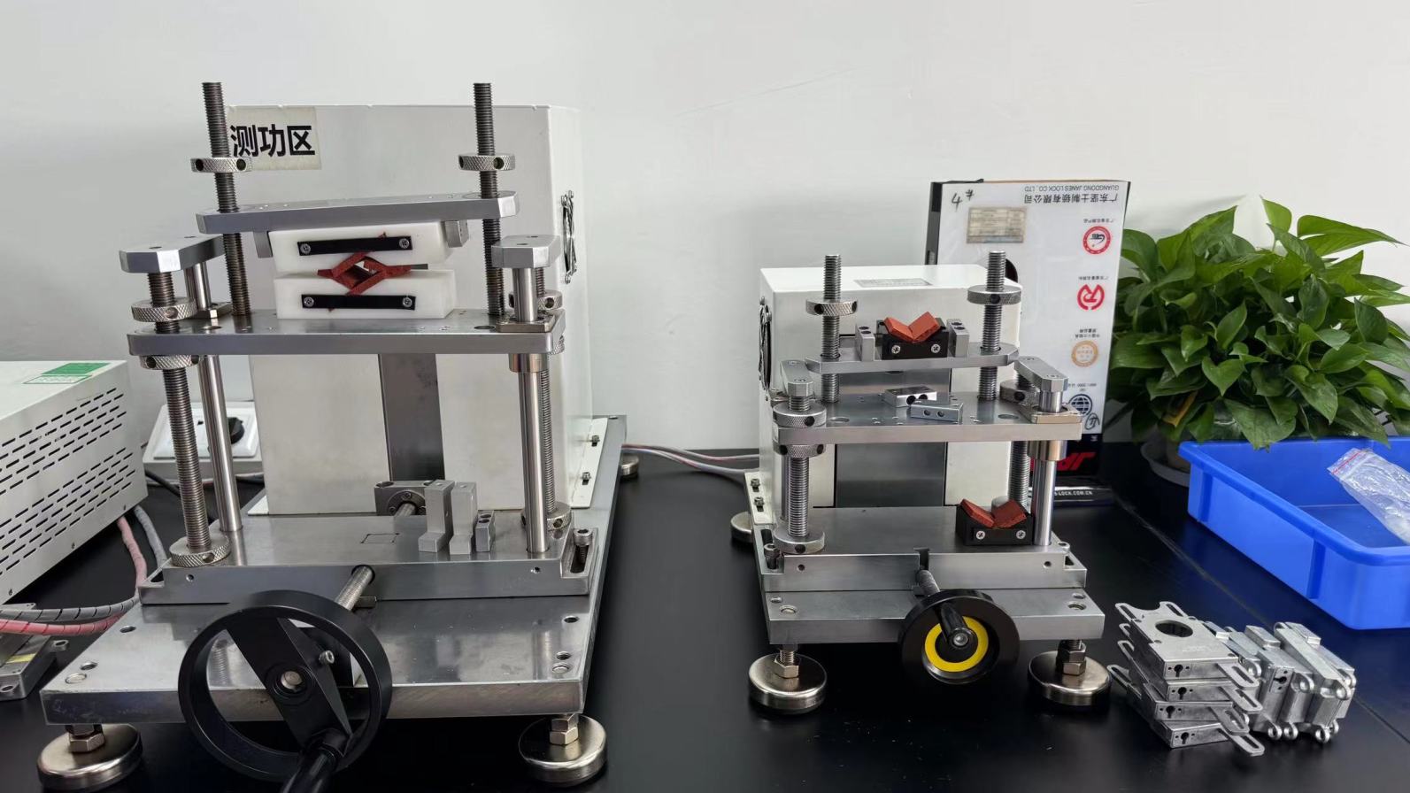
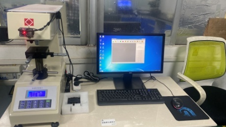
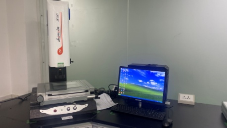
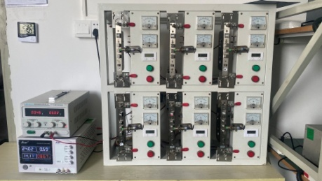
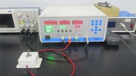
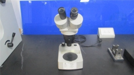
Metrology & Diagnostic Lab Assets
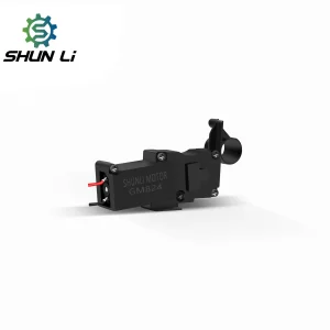
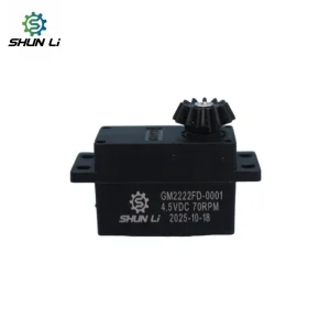
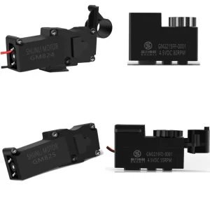
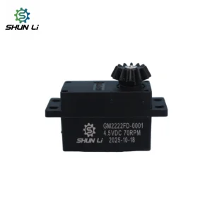
Primary Smart Lock Motor Catalog
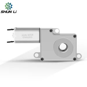
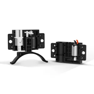
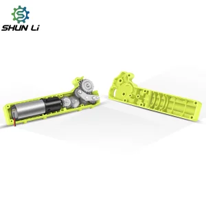
Explore our complete product catalog, featuring 3V, 4.5V, 6V, and 12V configurations that are ready for immediate integration into lock assembly lines.
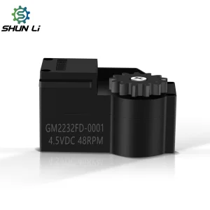
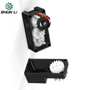
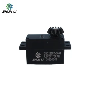
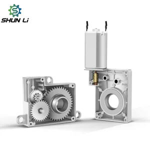
Specialized & Custom Geared Motors
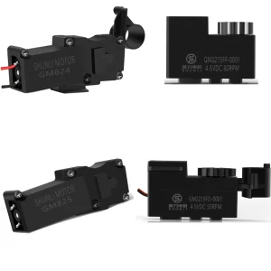
These permanent magnet brush systems offer custom RPM scaling for complex commercial access panels.
Technical Specification & Integration FAQ
Technical answers to common engineering questions regarding the customization and integration of lock motors.
Connect Directly With Our Engineering Office
Download custom 2D drawings, 3D CAD step files, or request testing samples for evaluation.
Request Technical Consultation